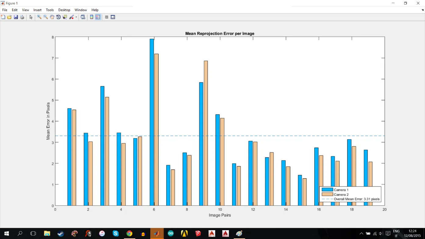
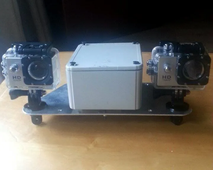
我正在尝试使用计算机视觉系统工具箱来校准下面的一对摄像头,以便能够在1到5米范围内生成车辆的三维点云。这些检查板标定图像的输出图像大小约为每张1 MB,检查板方格尺寸为25毫米。所使用的摄像头是一对SJ4000 HD1080P摄像头。这些摄像头被尽可能平行地放置在一起,并且垂直轴上没有任何角度。通过明亮的灯光和白板辅助进行了检查板标定。使用立体相机校准器代码时每个像素的平均误差为3.31,有31/32次成功配对。检查板距离大约为30厘米,相机之间的距离为20厘米。
 在矫正过程中遇到的问题是场景的三维重建。下面的图是输出的结果。我不确定相机设置中是否缺少参数,或者脚本中是否缺少/需要添加某些内容。下面是用于立体眼镜和场景重建的代码,该代码改编自Matlab立体相机校准教程。
% Read in the stereo pair of images.
I1 = imread('left.jpg');
I2 = imread('right.jpg');
% Rectify the images.
[J1, J2] = rectifyStereoImages(I1, I2, stereoParams);
% Display the images before rectification.
figure;
imshow(stereoAnaglyph(I1, I2), 'InitialMagnification', 50);
title('Before Rectification');
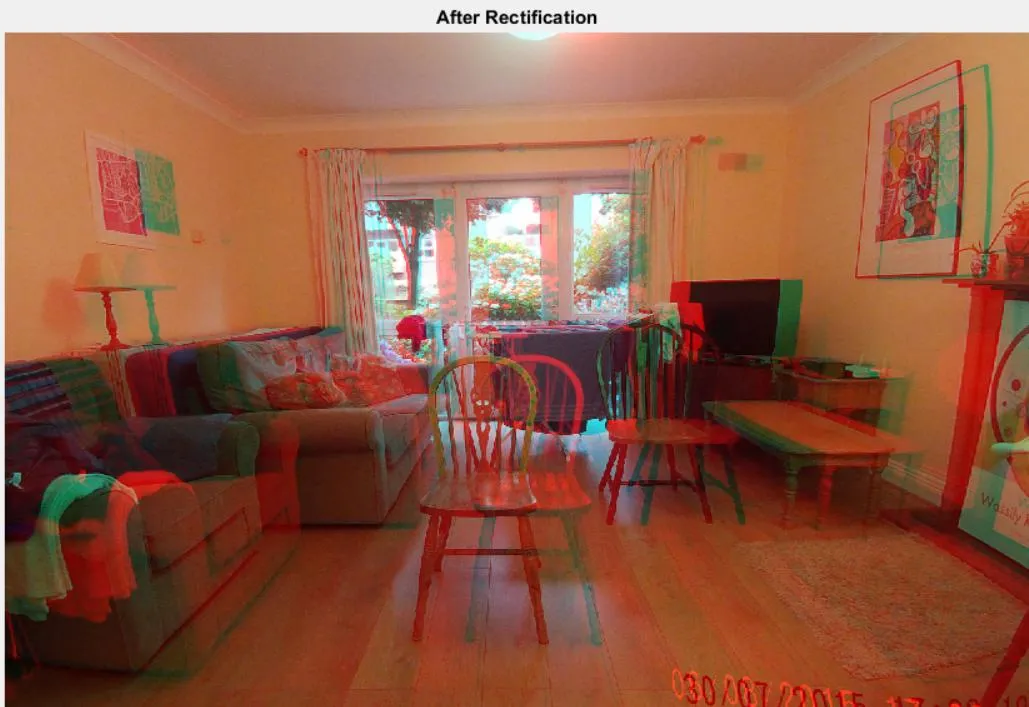
% Display the images after rectification.
figure;
imshow(stereoAnaglyph(J1, J2), 'InitialMagnification', 50);
title('After Rectification');
%
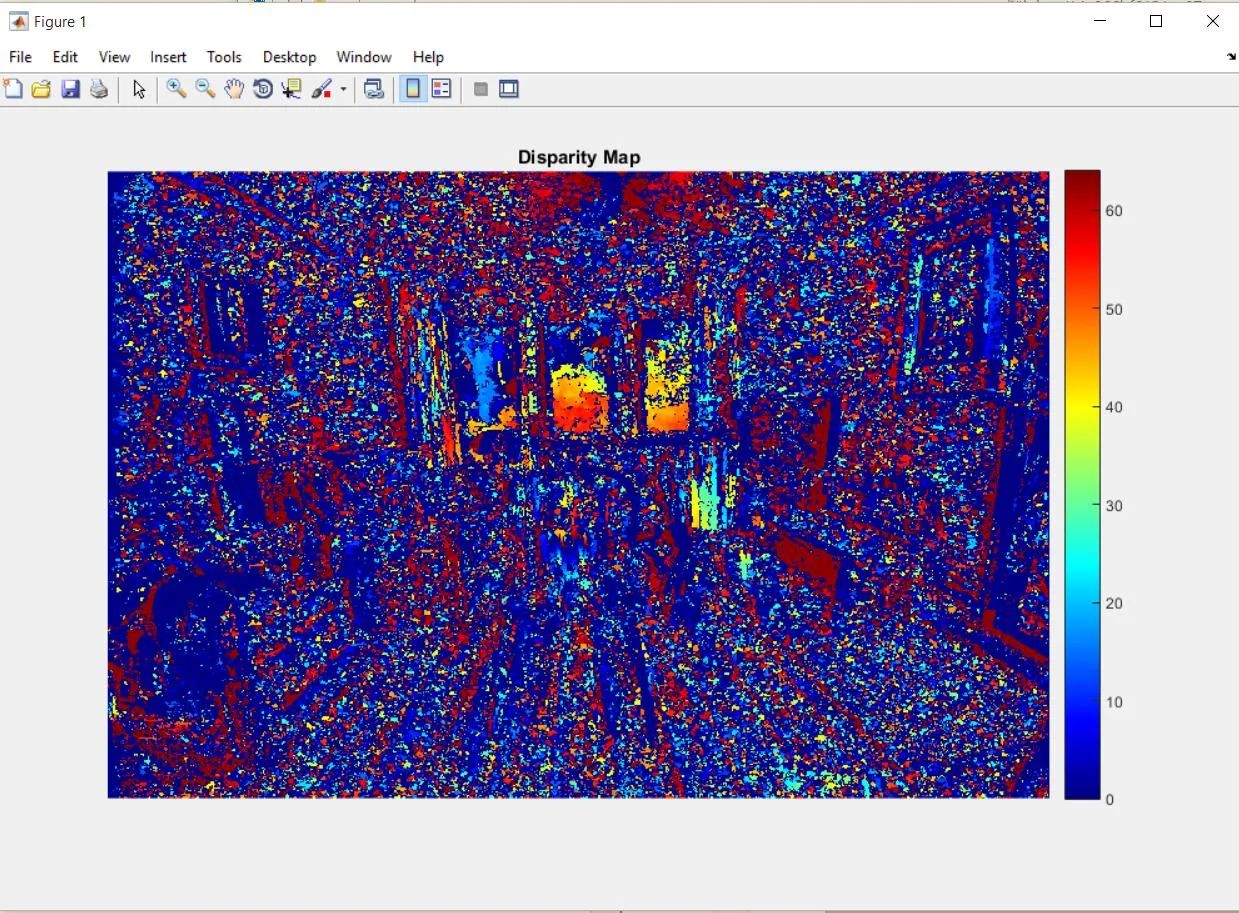
% Compute Disparity for 3-D Reconstruction
% The distance in pixels between corresponding points in the rectified images is called disparity.
% The disparity is used for 3-D reconstruction, because it is proportional to the distance between the cameras and the 3-D world point.
disparityMap = disparity(rgb2gray(J1), rgb2gray(J2));
figure;
imshow(disparityMap, [0, 64], 'InitialMagnification', 50);
colormap('jet');
colorbar;
title('Disparity Map');
%Reconstruct the 3-D Scene
%Reconstruct the 3-D world coordinates of points corresponding to each pixel from the disparity map.
point3D = reconstructScene(disparityMap, stereoParams);
% Convert from millimeters to meters.
point3D = point3D / 1000;
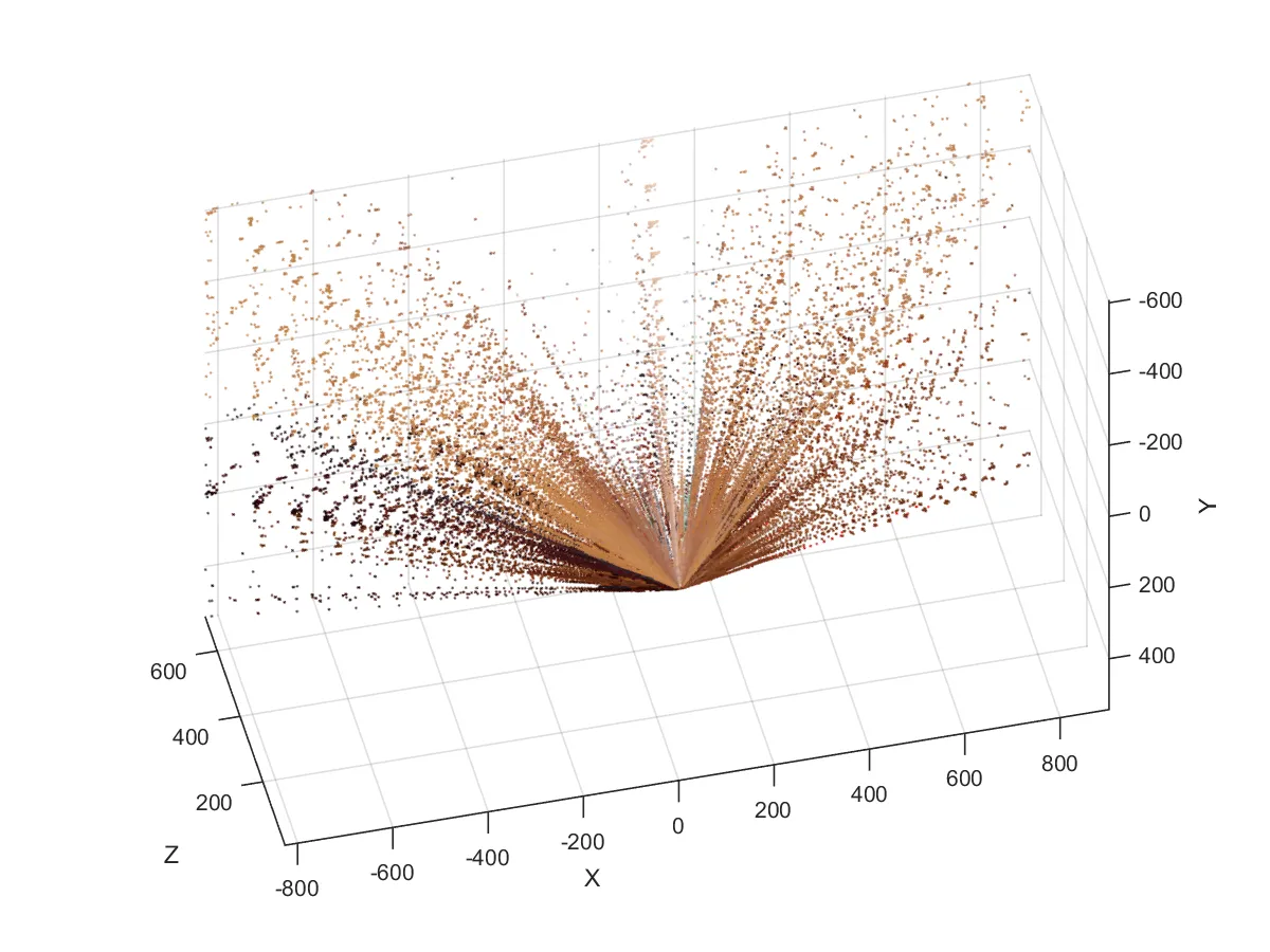
% Visualize the 3-D Scene
% Plot points between 3 and 7 meters away from the camera.
z = point3D(:, :, 3);
zdisp = z;
point3Ddisp = point3D;
point3Ddisp(:,:,3) = zdisp;
showPointCloud(point3Ddisp, J1, 'VerticalAxis', 'Y',...
'VerticalAxisDir', 'Down' );
xlabel('X');
ylabel('Y');
zlabel('Z');
我已经包含了场景重建、视差图、每像素平均误差和矫正后的图片。我使用的Matlab版本是从Matlab网站购买的R2014b学生版。