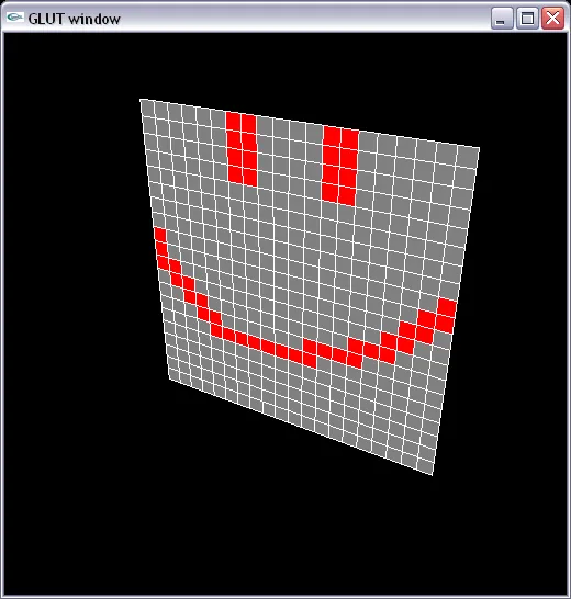
我正在开发一个绘制100x100网格并允许用户单击单元格更改颜色的程序。
目前单击功能已经实现,但仅当从正面观察网格时(即
我最近几天卡在了从不同相机位置或不同屏幕区域查看网格时选择正确单元格上。
我的唯一猜测是深度缓冲区可能没有反映出相机的当前位置,或者缓冲区深度范围与相机的近和远值之间存在某些不一致。或者我应用投影/视图矩阵的方式可以用于显示图像,但在回传到管道时出现了问题。但我无法完全弄清楚。
(代码已更新/重构自原始发布) 顶点着色器:
目前单击功能已经实现,但仅当从正面观察网格时(即
camPos.z等于camLook.z),并且网格位于屏幕中心时才有效。我最近几天卡在了从不同相机位置或不同屏幕区域查看网格时选择正确单元格上。
我的唯一猜测是深度缓冲区可能没有反映出相机的当前位置,或者缓冲区深度范围与相机的近和远值之间存在某些不一致。或者我应用投影/视图矩阵的方式可以用于显示图像,但在回传到管道时出现了问题。但我无法完全弄清楚。
(代码已更新/重构自原始发布) 顶点着色器:
#version 330

layout(location = 0) in vec4 position;

smooth out vec4 theColor;

uniform vec4 color;
uniform mat4 pv;

void main() {
  gl_Position = pv * position;
  theColor = color;
}
相机类(由projectionViewMatrix()的结果pv uniform生成):
Camera::Camera()
{
  camPos = glm::vec3(1.0f, 5.0f, 2.0f);
  camLook = glm::vec3(1.0f, 0.0f, 0.0f);

  fovy = 90.0f;
  aspect = 1.0f;
  near = 0.1f;
  far = 1000.0f;
}

glm::mat4 Camera::projectionMatrix()
{
  return glm::perspective(fovy, aspect, near, far);
}

glm::mat4 Camera::viewMatrix()
{
  return glm::lookAt(
    camPos,
    camLook,
    glm::vec3(0.0f, 1.0f, 0.0f)
  );
}

glm::mat4 Camera::projectionViewMatrix()
{
  return projectionMatrix() * viewMatrix();
}

// view controls

void Camera::moveForward()
{
  camPos.z -= 1.0f;
  camLook.z -= 1.0f;
}

void Camera::moveBack()
{
  camPos.z += 1.0f;
  camLook.z += 1.0f;
}

void Camera::moveLeft()
{
  camPos.x -= 1.0f;
  camLook.x -= 1.0f;
}

void Camera::moveRight()
{
  camPos.x += 1.0f;
  camLook.x += 1.0f;
}

void Camera::zoomIn()
{
  camPos.y -= 1.0f;
}

void Camera::zoomOut()
{
  camPos.y += 1.0f;
}

void Camera::lookDown()
{
  camLook.z += 0.1f;
}

void Camera::lookAtAngle()
{
  if (camLook.z != 0.0f)
    camLook.z -= 0.1f;
}
我正在尝试获取世界坐标的相机类中的特定函数(x和y是屏幕坐标):
glm::vec3 Camera::experiment(int x, int y)
{
  GLint viewport[4];
  glGetIntegerv(GL_VIEWPORT, viewport);

  GLfloat winZ;
  glReadPixels(x, y, 1, 1, GL_DEPTH_COMPONENT, GL_FLOAT, &winZ);
  printf("DEPTH: %f\n", winZ);

  glm::vec3 pos = glm::unProject(
    glm::vec3(x, viewport[3] - y, winZ),
    viewMatrix(),
    projectionMatrix(),
    glm::vec4(0.0f, 0.0f, viewport[2], viewport[3])
  );

  printf("POS: (%f, %f, %f)\n", pos.x, pos.y, pos.z);

  return pos;
}
初始化和展示:
void init(void)
{
  glewExperimental = GL_TRUE;
  glewInit();

  glEnable(GL_DEPTH_TEST);
  glDepthMask(GL_TRUE);
  glDepthFunc(GL_LESS);
  glDepthRange(0.0f, 1.0f);

  InitializeProgram();
  InitializeVAO();
  InitializeGrid();

  glEnable(GL_CULL_FACE);
  glCullFace(GL_BACK);
  glFrontFace(GL_CW);
}

void display(void)
{
  glClearColor(0.0f, 0.0f, 0.0f, 0.0f);
  glClear(GL_COLOR_BUFFER_BIT | GL_DEPTH_BUFFER_BIT);

  glUseProgram(theProgram);
  glBindVertexArray(vao);

  glUniformMatrix4fv(projectionViewMatrixUnif, 1, GL_FALSE, glm::value_ptr(camera.projectionViewMatrix()));

  DrawGrid();

  glBindVertexArray(0);
  glUseProgram(0);

  glutSwapBuffers();
  glutPostRedisplay();
}

int main(int argc, char** argv)
{
  glutInit(&argc, argv);

  glutInitDisplayMode(GLUT_RGB | GLUT_DEPTH);
  glutInitContextVersion(3, 2);
  glutInitContextProfile(GLUT_CORE_PROFILE);

  glutInitWindowSize(500, 500);
  glutInitWindowPosition(300, 200);

  glutCreateWindow("testing");

  init();

  glutDisplayFunc(display);
  glutReshapeFunc(reshape);
  glutKeyboardFunc(keyboard);
  glutMouseFunc(mouse);
  glutMainLoop();
  return 0;
}
glm::unProject (...)并不知道,因为它没有在你的变换矩阵中。按照你当前的方式,对于任何非零偏移量,都不应该正确工作。 - Andon M. Coleman