如何将一个3D点转换为2D透视投影?

76

我目前正在使用贝塞尔曲线和曲面来绘制著名的犹他茶壶。使用16个控制点的贝塞尔块,我已经能够绘制出茶壶并使用“世界到相机”函数显示茶壶,该函数可以旋转结果中的茶壶,并且我目前正在使用正交投影。

因此,我得到了一个“平面”的茶壶,这是预期的,因为正交投影的目的是保持平行线。

然而,我想使用透视投影使茶壶更加有深度。我的问题是,如何将从“世界到相机”函数返回的3D xyz顶点转换为2D坐标。我希望在z = 0处使用投影平面,并允许用户使用键盘上的箭头键确定焦距和图像大小。

我正在使用Java进行编程,并且已经设置好了所有输入事件处理程序,并且还编写了一个处理基本矩阵乘法的矩阵类。我已经阅读了维基百科和其他资源一段时间,但我仍无法完全掌握如何执行此转换。


https://dev59.com/h3RB5IYBdhLWcg3wJklC#701978 - erickson
一个非常好的交互式示例,展示了如何将三维点投影在二维空间中。链接为 http://www.mathdisk.com/pub/safi/worksheets/Perspective_Projection。 - user1509461
你在这方面有进展吗?我对这个任务中的Bezier部分有一些问题,可以在这里[https://dev59.com/g23Xa4cB1Zd3GeqPiL-c]和[https://dev59.com/6W7Xa4cB1Zd3GeqPoU-I]找到答案。 - luser droog
10个回答

121

现在表示2D / 3D变换的标准方法是使用齐次坐标。 2D为[x,y,w],3D为[x,y,z,w]。由于在3D中有三个轴以及平移,因此该信息完美地适合4x4变换矩阵中。在本说明中,我将使用列主要矩阵符号。除非另有说明,否则所有矩阵均为4x4。
从3D点到光栅化的点,线或多边形的阶段如下:

  1. 使用逆相机矩阵转换您的3D点,然后进行任何所需的变换。如果有表面法线,请将它们转换为零设置的w,因为您不想平移法线。您用于转换法线的矩阵必须是各向同性的;缩放和剪切会使法线畸形。
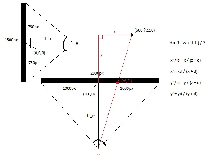
  2. 使用裁剪空间矩阵转换点。该矩阵使用视场角和宽高比缩放x和y,使用近和远裁剪平面缩放z,并将“旧”z插入w。变换后,应通过w除以x、y和z。这称为透视除法。
  3. 现在,您的顶点位于裁剪空间中,您希望执行裁剪,以便不渲染视口范围外的任何像素。Sutherland-Hodgeman裁剪是最广泛使用的裁剪算法。
  4. 相对于w和半宽度和半高度转换x和y。现在,您的x和y坐标位于视口坐标中。舍弃w,但通常保存1/w和z,因为需要1/w才能在多边形表面上进行透视校正插值,并且z存储在z缓冲区中并用于深度测试。

这个阶段是实际的投影,因为z不再用作位置的组成部分。

算法:

计算视场角

这个计算视野的范围。tan函数使用弧度或角度均可,但是angle必须匹配。请注意,当angle接近180度时,结果会趋近于无穷大。这是一个奇点,因为不可能有如此宽的焦点。如果想要数值稳定性,请将angle保持小于等于179度。

fov = 1.0 / tan(angle/2.0)

请注意,1.0 / tan(45) = 1。这里有人建议只需除以z。结果很清楚。您将获得90度的视场角和1:1的宽高比。像这样使用齐次坐标还有其他几个优点;例如,我们可以执行针对近平面和远平面的裁剪而不将其视为特殊情况。

计算剪辑矩阵

这是剪辑矩阵的布局。aspectRatio是宽度/高度。因此,x分量的FOV基于y分量的FOV进行缩放。Far和near是系数,它们是近和远裁剪平面的距离。

[fov * aspectRatio][        0        ][        0              ][        0       ]
[        0        ][       fov       ][        0              ][        0       ]
[        0        ][        0        ][(far+near)/(far-near)  ][        1       ]
[        0        ][        0        ][(2*near*far)/(near-far)][        0       ]

屏幕投影

剪裁之后,这是获取屏幕坐标的最终转换。

new_x = (x * Width ) / (2.0 * w) + halfWidth;
new_y = (y * Height) / (2.0 * w) + halfHeight;

C++中的简单示例实现

#include <vector>
#include <cmath>
#include <stdexcept>
#include <algorithm>

struct Vector
{
    Vector() : x(0),y(0),z(0),w(1){}
    Vector(float a, float b, float c) : x(a),y(b),z(c),w(1){}

    /* Assume proper operator overloads here, with vectors and scalars */
    float Length() const
    {
        return std::sqrt(x*x + y*y + z*z);
    }
    
    Vector Unit() const
    {
        const float epsilon = 1e-6;
        float mag = Length();
        if(mag < epsilon){
            std::out_of_range e("");
            throw e;
        }
        return *this / mag;
    }
};

inline float Dot(const Vector& v1, const Vector& v2)
{
    return v1.x*v2.x + v1.y*v2.y + v1.z*v2.z;
}

class Matrix
{
    public:
    Matrix() : data(16)
    {
        Identity();
    }
    void Identity()
    {
        std::fill(data.begin(), data.end(), float(0));
        data[0] = data[5] = data[10] = data[15] = 1.0f;
    }
    float& operator[](size_t index)
    {
        if(index >= 16){
            std::out_of_range e("");
            throw e;
        }
        return data[index];
    }
    Matrix operator*(const Matrix& m) const
    {
        Matrix dst;
        int col;
        for(int y=0; y<4; ++y){
            col = y*4;
            for(int x=0; x<4; ++x){
                for(int i=0; i<4; ++i){
                    dst[x+col] += m[i+col]*data[x+i*4];
                }
            }
        }
        return dst;
    }
    Matrix& operator*=(const Matrix& m)
    {
        *this = (*this) * m;
        return *this;
    }

    /* The interesting stuff */
    void SetupClipMatrix(float fov, float aspectRatio, float near, float far)
    {
        Identity();
        float f = 1.0f / std::tan(fov * 0.5f);
        data[0] = f*aspectRatio;
        data[5] = f;
        data[10] = (far+near) / (far-near);
        data[11] = 1.0f; /* this 'plugs' the old z into w */
        data[14] = (2.0f*near*far) / (near-far);
        data[15] = 0.0f;
    }

    std::vector<float> data;
};

inline Vector operator*(const Vector& v, const Matrix& m)
{
    Vector dst;
    dst.x = v.x*m[0] + v.y*m[4] + v.z*m[8 ] + v.w*m[12];
    dst.y = v.x*m[1] + v.y*m[5] + v.z*m[9 ] + v.w*m[13];
    dst.z = v.x*m[2] + v.y*m[6] + v.z*m[10] + v.w*m[14];
    dst.w = v.x*m[3] + v.y*m[7] + v.z*m[11] + v.w*m[15];
    return dst;
}

typedef std::vector<Vector> VecArr;
VecArr ProjectAndClip(int width, int height, float near, float far, const VecArr& vertex)
{
    float halfWidth = (float)width * 0.5f;
    float halfHeight = (float)height * 0.5f;
    float aspect = (float)width / (float)height;
    Vector v;
    Matrix clipMatrix;
    VecArr dst;
    clipMatrix.SetupClipMatrix(60.0f * (M_PI / 180.0f), aspect, near, far);
    /*  Here, after the perspective divide, you perform Sutherland-Hodgeman clipping 
        by checking if the x, y and z components are inside the range of [-w, w].
        One checks each vector component seperately against each plane. Per-vertex
        data like colours, normals and texture coordinates need to be linearly
        interpolated for clipped edges to reflect the change. If the edge (v0,v1)
        is tested against the positive x plane, and v1 is outside, the interpolant
        becomes: (v1.x - w) / (v1.x - v0.x)
        I skip this stage all together to be brief.
    */
    for(VecArr::iterator i=vertex.begin(); i!=vertex.end(); ++i){
        v = (*i) * clipMatrix;
        v /= v.w; /* Don't get confused here. I assume the divide leaves v.w alone.*/
        dst.push_back(v);
    }

    /* TODO: Clipping here */

    for(VecArr::iterator i=dst.begin(); i!=dst.end(); ++i){
        i->x = (i->x * (float)width) / (2.0f * i->w) + halfWidth;
        i->y = (i->y * (float)height) / (2.0f * i->w) + halfHeight;
    }
    return dst;
}

如果你还在思考这个问题,OpenGL规范是涉及数学的一个非常好的参考。Devmaster论坛http://www.devmaster.net/上有很多与软件光栅化器相关的好文章。

3
这句话的意思是,通过检查 x、y 和 z 分量是否在范围 [-w, w] 内来执行 Sutherland-Hodgeman 剪切。其中的 -w 和 w 指代的是剪裁体积的左右边界。这些值通常在将物体从世界空间转换到标准设备空间时设置。 - petersaints
3
那个“微不足道”的例子甚至不能编译。 - kungfooman

26
我认为这篇文章可能会回答你的问题。以下是我在那里写的内容:
这是一个非常普遍的答案。 假设相机位于(Xc,Yc,Zc),您要投影的点是P =(X,Y,Z)。 从相机到您要投射的2D平面的距离为F(因此平面的方程式为Z-Zc = F)。 投影到平面上的P的2D坐标为(X',Y')。 然后,简单地说: X' = ((X - Xc) * (F/Z)) + Xc Y' = ((Y - Yc) * (F/Z)) + Yc 如果您的相机在原点,则简化为: X' = X * (F/Z) Y' = Y * (F/Z)

12

要获取透视校正后的坐标,只需通过z坐标进行除法运算:

xc = x / z
yc = y / z

假设相机在(0, 0, 0)处,你正在将其投影到z = 1的平面上——否则你需要相对于相机来翻译坐标。

对于曲线存在一些复杂性,因为投影一个三维贝塞尔曲线的点通常不会给出通过投影点绘制的二维贝塞尔曲线的相同点。


10

只需使用两个类,即可使用Commons Math: The Apache Commons Mathematics Library将3D点投影到2D上。

Java Swing示例。

import org.apache.commons.math3.geometry.euclidean.threed.Plane;
import org.apache.commons.math3.geometry.euclidean.threed.Vector3D;


Plane planeX = new Plane(new Vector3D(1, 0, 0));
Plane planeY = new Plane(new Vector3D(0, 1, 0)); // Must be orthogonal plane of planeX

void drawPoint(Graphics2D g2, Vector3D v) {
    g2.drawLine(0, 0,
            (int) (world.unit * planeX.getOffset(v)),
            (int) (world.unit * planeY.getOffset(v)));
}

protected void paintComponent(Graphics g) {
    super.paintComponent(g);

    drawPoint(g2, new Vector3D(2, 1, 0));
    drawPoint(g2, new Vector3D(0, 2, 0));
    drawPoint(g2, new Vector3D(0, 0, 2));
    drawPoint(g2, new Vector3D(1, 1, 1));
}

现在您只需要更新planeXplaneY来改变透视投影,就可以得到如下的效果:

enter image description hereenter image description here


8

进入图像描述

从上面看屏幕,你会得到x和z轴。
从侧面看屏幕,您将得到y和z轴。

使用三角函数计算顶部和侧面视图的焦距,即眼睛与屏幕中心之间的距离,这是由屏幕的视野决定的。 这使得两个直角三角形背对背。

hw = 屏幕宽度 / 2

hh = 屏幕高度 / 2

fl_top = hw / tan(θ/2)

fl_side = hh / tan(θ/2)


然后取平均焦距。

fl_average = (fl_top + fl_side) / 2


现在用基本算术计算新的x和新的y,因为由3D点和眼点组成的较大直角三角形与由2D点和眼点组成的较小三角形是全等的。

x' = (x * fl_top) / (z + fl_top)

y' = (y * fl_top) / (z + fl_top)


或者你可以简单地设置

x' = x / (z + 1)

y' = y / (z + 1)


2
感谢@Mads Elvenheim提供的适当示例代码。我已经修复了代码中的一些小语法错误(仅涉及少量的const问题和明显缺失的运算符)。此外,在vs中,nearfar具有非常不同的含义。
为了您的方便,这里是可编译的(MSVC2013)版本。玩得开心。 请注意,我已经将NEAR_Z和FAR_Z设为常量。您可能不想这样做。
#include <vector>
#include <cmath>
#include <stdexcept>
#include <algorithm>

#define M_PI 3.14159

#define NEAR_Z 0.5
#define FAR_Z 2.5

struct Vector
{
    float x;
    float y;
    float z;
    float w;

    Vector() : x( 0 ), y( 0 ), z( 0 ), w( 1 ) {}
    Vector( float a, float b, float c ) : x( a ), y( b ), z( c ), w( 1 ) {}

    /* Assume proper operator overloads here, with vectors and scalars */
    float Length() const
    {
        return std::sqrt( x*x + y*y + z*z );
    }
    Vector& operator*=(float fac) noexcept
    {
        x *= fac;
        y *= fac;
        z *= fac;
        return *this;
    }
    Vector  operator*(float fac) const noexcept
    {
        return Vector(*this)*=fac;
    }
    Vector& operator/=(float div) noexcept
    {
        return operator*=(1/div);   // avoid divisions: they are much
                                    // more costly than multiplications
    }

    Vector Unit() const
    {
        const float epsilon = 1e-6;
        float mag = Length();
        if (mag < epsilon) {
            std::out_of_range e( "" );
            throw e;
        }
        return Vector(*this)/=mag;
    }
};

inline float Dot( const Vector& v1, const Vector& v2 )
{
    return v1.x*v2.x + v1.y*v2.y + v1.z*v2.z;
}

class Matrix
{
public:
    Matrix() : data( 16 )
    {
        Identity();
    }
    void Identity()
    {
        std::fill( data.begin(), data.end(), float( 0 ) );
        data[0] = data[5] = data[10] = data[15] = 1.0f;
    }
    float& operator[]( size_t index )
    {
        if (index >= 16) {
            std::out_of_range e( "" );
            throw e;
        }
        return data[index];
    }
    const float& operator[]( size_t index ) const
    {
        if (index >= 16) {
            std::out_of_range e( "" );
            throw e;
        }
        return data[index];
    }
    Matrix operator*( const Matrix& m ) const
    {
        Matrix dst;
        int col;
        for (int y = 0; y<4; ++y) {
            col = y * 4;
            for (int x = 0; x<4; ++x) {
                for (int i = 0; i<4; ++i) {
                    dst[x + col] += m[i + col] * data[x + i * 4];
                }
            }
        }
        return dst;
    }
    Matrix& operator*=( const Matrix& m )
    {
        *this = (*this) * m;
        return *this;
    }

    /* The interesting stuff */
    void SetupClipMatrix( float fov, float aspectRatio )
    {
        Identity();
        float f = 1.0f / std::tan( fov * 0.5f );
        data[0] = f*aspectRatio;
        data[5] = f;
        data[10] = (FAR_Z + NEAR_Z) / (FAR_Z- NEAR_Z);
        data[11] = 1.0f; /* this 'plugs' the old z into w */
        data[14] = (2.0f*NEAR_Z*FAR_Z) / (NEAR_Z - FAR_Z);
        data[15] = 0.0f;
    }

    std::vector<float> data;
};


inline Vector operator*( const Vector& v, Matrix& m )
{
    Vector dst;
    dst.x = v.x*m[0] + v.y*m[4] + v.z*m[8] + v.w*m[12];
    dst.y = v.x*m[1] + v.y*m[5] + v.z*m[9] + v.w*m[13];
    dst.z = v.x*m[2] + v.y*m[6] + v.z*m[10] + v.w*m[14];
    dst.w = v.x*m[3] + v.y*m[7] + v.z*m[11] + v.w*m[15];
    return dst;
}

typedef std::vector<Vector> VecArr;
VecArr ProjectAndClip( int width, int height, const VecArr& vertex )
{
    float halfWidth = (float)width * 0.5f;
    float halfHeight = (float)height * 0.5f;
    float aspect = (float)width / (float)height;
    Vector v;
    Matrix clipMatrix;
    VecArr dst;
    clipMatrix.SetupClipMatrix( 60.0f * (M_PI / 180.0f), aspect);
    /*  Here, after the perspective divide, you perform Sutherland-Hodgeman clipping
    by checking if the x, y and z components are inside the range of [-w, w].
    One checks each vector component seperately against each plane. Per-vertex
    data like colours, normals and texture coordinates need to be linearly
    interpolated for clipped edges to reflect the change. If the edge (v0,v1)
    is tested against the positive x plane, and v1 is outside, the interpolant
    becomes: (v1.x - w) / (v1.x - v0.x)
    I skip this stage all together to be brief.
    */
    for (VecArr::const_iterator i = vertex.begin(); i != vertex.end(); ++i) {
        v = (*i) * clipMatrix;
        v /= v.w; /* Don't get confused here. I assume the divide leaves v.w alone.*/
        dst.push_back( v );
    }

    /* TODO: Clipping here */

    for (VecArr::iterator i = dst.begin(); i != dst.end(); ++i) {
        i->x = (i->x * (float)width) / (2.0f * i->w) + halfWidth;
        i->y = (i->y * (float)height) / (2.0f * i->w) + halfHeight;
    }
    return dst;
}
#pragma once

这是一段可怕的代码。例如你的operator/ =浪费了2个除法并返回了一个对临时变量的引用。相反它应该改变“this”并返回* this。此外,这是C ++,但问题是Java。 - Walter
@Walter,我已经修复了对临时引用的危险引用,感谢您通知我。正如我在答案中所述,这只是Mads Elvenheims答案的可编译版本;我并没有说这很有效率,但它帮助我理解了细节,因此我想分享它。关于Java vs C ++,我复制到这里的 accepted 答案也是用C ++编写的。 - antipattern
1
根据您的建议,将operator/=更改了。您是对的,它应该改变向量本身。 - antipattern
我已编辑了你的代码。希望你不介意。另外,为什么你在 Unit() 中如果长度小于1e-6就抛出一个错误呢?如果三个向量分量都更小怎么办?要么什么都不做(如果长度为0则返回NaN),要么只检查长度是否等于0。 - Walter
@Walter 感谢您的建议。我刚刚修复了被接受答案中明显的编译器错误;这些设计问题超出了我的修复范围。 - antipattern
显示剩余2条评论

2

我不确定您提问的水平。看起来您已经在网上找到了公式,现在只是想理解它的作用。如果您的问题是这样的,我可以给出以下回答:

  • 想象一个从观察者(点V)向投影平面中心(称为C)直接射出的光线。
  • 想象第二条从观察者到图像中某一点(P)的光线,该光线也与投影平面在某一点(Q)相交。
  • 观察者和视图平面上两个相交点形成一个三角形(VCQ),其边是两条光线和平面内两点之间的直线。
  • 这些公式使用这个三角形来找到Q的坐标,即投影像素所在的位置。

1
实际上恰恰相反 - 我已经找到了几个关于投影平面的图表和解释,但我还没有开始编写任何代码,因为我没有公式可供使用。我甚至不确定你所提到的“公式”是什么。 - Zachary Wright
1
@Zachary -- 其他两个答案中包含的公式,维基百科页面等等。基本上 X' = (X-C1)*C2/Z + C3,Y同理。 - MarkusQ

1
所有的答案都回答了标题所提出的问题。但是,我想添加一个隐含在文本中的警告。Bézier贴片用于表示曲面,但你不能只是转换贴片的点并将贴片分解成多边形,因为这会导致几何形状失真。但是你可以先将贴片细分成多边形,使用变换后的屏幕公差,然后再对多边形进行变换;或者你可以将Bézier贴片转换为有理Bézier贴片,然后使用屏幕空间公差对它们进行细分。前者更容易,但后者更适合生产系统。
我猜你想要更容易的方法。为此,你需要通过逆透视变换的雅可比矩阵范数来缩放屏幕公差,并使用它来确定模型空间需要的细分量(可能更容易计算正向雅可比矩阵,然后取其倒数)。请注意,这个范数是位置相关的,你可能需要根据透视图在不同位置进行评估。还要记住,由于投影变换是有理的,你需要应用商规则来计算导数。

0

我知道这是一个老话题,但你的插图不正确,源代码设置剪辑矩阵是正确的。

[fov * aspectRatio][        0        ][        0              ][        0       ]
[        0        ][       fov       ][        0              ][        0       ]
[        0        ][        0        ][(far+near)/(far-near)  ][(2*near*far)/(near-far)]
[        0        ][        0        ][        1              ][        0       ]

关于您的事项,有一些补充:

这个剪辑矩阵仅在您投影到静态二维平面时才有效,如果您想要添加相机移动和旋转:

viewMatrix = clipMatrix * cameraTranslationMatrix4x4 * cameraRotationMatrix4x4;

这让你可以旋转2D平面并将其移动..-


2
不,你错了。这取决于你使用的是列优先还是行优先表示法。你想的是OpenGL,它使用列优先。 - Stas Jaro

0

你可能想使用球体来调试你的系统,以确定你是否拥有良好的视野。如果你的视野太宽,球体在屏幕边缘会变形成更椭圆形状,指向框架中心。解决这个问题的方法是通过将三维点的x和y坐标乘以一个标量来放大框架,然后通过类似的因子缩小你的对象或世界。然后你就可以获得整个框架上漂亮均匀的圆形球体。

我几乎感到尴尬,因为我花了一整天才弄清楚这个问题,而且我几乎相信这里存在某种神秘的几何现象,需要不同的方法来解决。

然而,通过渲染球体校准缩放-视野系数的重要性不言而喻。如果你不知道你的宇宙的“适居区”在哪里,你最终会走在太阳上并放弃这个项目。你希望能够在你的视野范围内的任何地方渲染一个球体,并使其呈现出圆形。在我的项目中,单位球体与我描述的区域相比非常巨大。

此外,还有义务的维基百科条目: 球坐标系


网页内容由stack overflow 提供, 点击上面的
可以查看英文原文,
原文链接