如何从零开始组合一个具有可读性的旋转矩阵,其中包含人类可读的角度?

37

我一直被数学难倒,无法进行3D编程。在编程流程中使用方法和函数时,我可以很好地理解数学,一切都很清晰和合乎逻辑。但是在数学符号中,我就是看不懂。

我一直在阅读网站并观看机构的视频,他们尝试解释这个问题,但他们都使用数学符号,我只会迷失其中,无法将其翻译成可理解的东西。我可能在这方面有缺陷。

此外,仅仅使用别人的代码并不是我的兴趣所在,我想要理解它的运作机制、逻辑。我很乐意使用别人的代码,但我真的想知道它是如何工作的。

问题

能否用简单易懂的术语而不使用数学符号,只用编程符号/函数/伪代码来解释如何在所有三个轴上实现矩阵变换?

理想情况下,我想要的是材料/理解,以编写一个方法/对象,在其中可以定义类似于glRotate的三个轴的角度,从而旋转我拥有的四边形/三角形收集体。(我正在尝试编写一个3D旋转立方体的程序,而没有访问OpenGL函数来完成这个操作,因为每次在显示列表中更改某些内容时,它都是在一个绘制调用中完成的。)

我做了什么?

我尝试制作一个90度变换函数,以掌握数学技巧,但在制作一个正确的矩阵方面却彻底失败了。您可以在http://jsfiddle.net/bLfg0tj8/5/上看到我的失败尝试。

Vec3 = function(x,y,z) {
    this.x = x;
    this.y = y;
    this.z = z;
}
Matrix = function Matrix() {
    this.matrixPoints = new Array();    
    this.rotationPoint = new Vec3(0,0,0);
    this.rotationAngle = 90;
}
Matrix.prototype.addVector = function(vector) {
    this.matrixPoints.push(vector);
}
Matrix.prototype.setRotationPoint = function(vector) {
    this.rotationPoint = vector; 
}
Matrix.prototype.setRotationAngle = function(angle) {
    this.rotationAngle = angle;
}
Matrix.prototype.populate = function() {
    translateToOrigin =     [[1,0,0-this.rotationPoint.x],
                                  [0,1,0-this.rotationPoint.y],
                                  [0,0,0-this.rotationPoint.z]];
    rotationMatrix =         [[0,-1,0],
                                  [0,1,0],
                                  [0,0,1]];
    translateEnd =         [[1,0,this.rotationPoint.x],
                                  [0,1,this.rotationPoint.y],
                                  [0,0,this.rotationPoint.z]];
    currentColumn = 0;
    currentRow = 0;
    this.combomatrix = this.mergeMatrices(this.mergeMatrices(translateEnd,rotationMatrix),
                                          translateToOrigin);
}
Matrix.prototype.transform = function() {
    newmatrix = new Array();
    for(c = 0;c<this.matrixPoints.length;c++) {
        newmatrix.push(this.applyToVertex(this.matrixPoints[c]));
    }
    return newmatrix;
}
Matrix.prototype.applyToVertex = function(vertex) {
    ret = new Vec3(vertex.x,vertex.y,vertex.z);
    ret.x = ret.x + this.combomatrix[0][0] * vertex.x +
            this.combomatrix[0][1] * vertex.y +
            this.combomatrix[0][2] * vertex.z;
    
    ret.y = ret.y + this.combomatrix[1][0] * vertex.x +
            this.combomatrix[1][1] * vertex.y +
            this.combomatrix[1][2] * vertex.z;
    
    ret.z = ret.z + this.combomatrix[2][0] * vertex.x +
            this.combomatrix[2][1] * vertex.y +
            this.combomatrix[2][2] * vertex.z;
    return ret;
}
Matrix.prototype.mergeMatrices = function(lastStep, oneInFront) {
    step1 = [[0,0,0],[0,0,0],[0,0,0]];
    step1[0][0] =   lastStep[0][0] * oneInFront[0][0] + 
                    lastStep[0][1] * oneInFront[1][0] + 
                    lastStep[0][2] * oneInFront[2][0];
    
    step1[0][1] =   lastStep[0][0] * oneInFront[0][1] + 
                    lastStep[0][1] * oneInFront[1][1] + 
                    lastStep[0][2] * oneInFront[2][1];
    
    step1[0][2] =   lastStep[0][0] * oneInFront[0][2] + 
                    lastStep[0][1] * oneInFront[1][2] + 
                    lastStep[0][2] * oneInFront[2][2];
    //============================================================
    step1[1][0] =   lastStep[1][0] * oneInFront[0][0] + 
                    lastStep[1][1] * oneInFront[1][0] + 
                    lastStep[1][2] * oneInFront[2][0];
    
    step1[1][1] =   lastStep[1][0] * oneInFront[0][1] + 
                    lastStep[1][1] * oneInFront[1][1] + 
                    lastStep[1][2] * oneInFront[2][1];
    
    step1[1][2] =   lastStep[1][0] * oneInFront[0][2] + 
                    lastStep[1][1] * oneInFront[1][2] + 
                    lastStep[1][2] * oneInFront[2][2];
    //============================================================
    step1[2][0] =   lastStep[2][0] * oneInFront[0][0] + 
                    lastStep[2][1] * oneInFront[1][0] + 
                    lastStep[2][2] * oneInFront[2][0];
    
    step1[2][1] =   lastStep[2][0] * oneInFront[0][1] + 
                    lastStep[2][1] * oneInFront[1][1] + 
                    lastStep[2][2] * oneInFront[2][1];
    
    step1[2][2] =   lastStep[2][0] * oneInFront[0][2] + 
                    lastStep[2][1] * oneInFront[1][2] + 
                    lastStep[2][2] * oneInFront[2][2];
    return step1;
}
Matrix.prototype.getCurrentMatrix = function() {
    return this.matrixPoints;
}
myvectors = [new Vec3(50,50,0), new Vec3(20,80,0), new Vec3(80, 80, 0)];

function drawVectors(vectors,color) {
    for(c=0;c<vectors.length;c++) {
        document.getElementById("whoa").innerHTML += '<div style="color:'+color+';position:absolute;left:'+vectors[c].x+'px; top:'+vectors[c].y+'px;z-index:'+vectors[c].z+';">('+c+').</div>';
    }
}
matrix = new Matrix();
for(c=0;c<myvectors.length;c++) {
    matrix.addVector(myvectors[c]);
}
matrix.setRotationPoint(new Vec3(50,70,0));
matrix.populate();
somematrix = matrix.transform();
drawVectors(matrix.getCurrentMatrix(),"lime"); // draw current matrix that was hand coded
drawVectors([matrix.rotationPoint],'white'); // draw rotation point
drawVectors(somematrix,"red"); // transformed matrix... somehow two points merge
<div id="whoa" style="position:relative;top:50px;left:150px;background-color:green;color:red;width:400px;height:300px;">
    &nbsp;
</div>

绿色的文字代表原始三角形,白点是中心点,红点表示失败的变换(我认为是因为它们没有围绕中心点对齐)。我学习的教程教我如何将矩阵组合成一个组合矩阵,但我想我在某个地方搞砸了。

正如我所说的,对于我来说,理解数学符号并进行讲解真的非常非常困难。而且更加不利的是,大多数老师都会跳过某些部分的解释。我花了两个小时才明白,在乘法矩阵时你需要将每一步加在一起,而不是以继续相乘的方式。感谢这样的解释。

一个我正在使用/想要使用的实际示例

例如,我有一个立方体,从位于世界中的Wavefront obj文件加载:

x = 50
y = 100
z = 200

这个立方体使用四边形和一些UV映射来绘制。没有问题。它可以渲染出美丽的效果,并正确显示所有纹理。

这些是每个“面”(由四边形绘制而成)的位置坐标。

// Front face
-1.0, -1.0,  1.0,
 1.0, -1.0,  1.0,
 1.0,  1.0,  1.0,
-1.0,  1.0,  1.0,

// Back face
-1.0, -1.0, -1.0,
-1.0,  1.0, -1.0,
 1.0,  1.0, -1.0,
 1.0, -1.0, -1.0,

// Top face
-1.0,  1.0, -1.0,
-1.0,  1.0,  1.0,
 1.0,  1.0,  1.0,
 1.0,  1.0, -1.0,

// Bottom face
-1.0, -1.0, -1.0,
 1.0, -1.0, -1.0,
 1.0, -1.0,  1.0,
-1.0, -1.0,  1.0,

// Right face
 1.0, -1.0, -1.0,
 1.0,  1.0, -1.0,
 1.0,  1.0,  1.0,
 1.0, -1.0,  1.0,

// Left face
-1.0, -1.0, -1.0,
-1.0, -1.0,  1.0,
-1.0,  1.0,  1.0,
-1.0,  1.0, -1.0

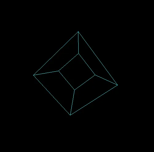
这很好地解决了问题。但是如果我想让这个立方体绕X轴旋转90度,绕Z轴旋转45度呢?我不能使用glRotate,因为在将数据传递给细分器对象的时候,我无法通过OpenGL函数对其进行任何矩阵变换,因为它只是接收数据,没有实际上渲染它。

数据的存储方式如下:

WaveFrontObject()
   |
   |-> Groups(String groupname)
        |
        |-> Faces()
              |
              |-> Vertex(float x, float y, float z)[] 
              |-> Float UVmap[] corresponding to each vertex
              |-> drawFace() // Draws the face as a quad or triangle

每个上述给出的坐标都作为波前对象中组“cube”的一个面存储。

当将立方体添加到填充器中时,它会被转换为世界中的正确坐标,并正常呈现。

但是它总是呈现相同的状态。如果我想让它以角度呈现,那么此时我必须制作一个单独的波前对象才能做到这一点。在我看来,这种方法在使用一些数学方法解决时就有些疯狂了。

需要回答的问题:

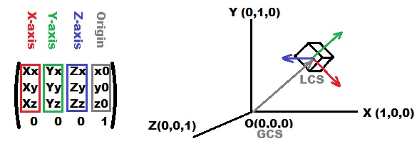
  1. 分步解释如何构建翻译矩阵以及试图向我解释其中的数学原理。
  2. 解释如何将翻译矩阵应用于四边形/三角形面,同时保持它们围绕其位置的中心保持定向
  3. 提供一些示例/伪代码以说明解释。

编程语言并不是很重要,只要是C家族的语言就可以。

请尽量避免使用数学符号/术语。我不知道什么是alpha beta, thetha,我知道什么是x轴、y轴和z轴。我知道什么是角度,但我不知道数学家为其取的名称是什么。

如果您想使用数学术语,请向我解释它们在3D世界/代码中是什么以及如何计算。

我只是想制作一个类似于以下内容的方法/对象:

Matrix.transformVertices(vertices[], 90deg x, 45 deg y, 0 deg z);

3
数学符号的整个目的就是使事情更易于理解。编程算法总是一般数学概念的特殊情况。当涉及到线性代数时,我认为你可能会发现这篇文章非常有用(特别是矩阵如何作为“函数”处理输入数据的片段):http://betterexplained.com/articles/linear-algebra-guide/ - datenwolf
2
你所问的是不可能的。当然,你可以复制和粘贴一个矩阵类或旋转方法,我相信你可以在网上找到很多。在其中,你会看到数组按照一些for循环方案相互相加和相乘。如果你知道数组和for循环,那么这就是你能够用纯编程而无需数学方式来理解它的最接近方法了。如果这对你来说还不够,你必须继续尝试学习数学。有时候,如果所有的教程都不符合你的思维方式,这可能很难,但也许你可以去参加一些当地的课程之类的东西。 - Thomas
虽然我会觉得很不好意思给这样一个仔细撰写的问题点踩,但我同意之前评论者的观点,这是一个棘手的要求。而且我认为这并不适合在SO上提问。用非数学符号解释数学概念几乎是自相矛盾的。即使这是相当基础的数学,如果需要从头开始解释每个细节,也需要大量的解释。尽管如此,如果我尝试一下,我仍然不确定自己是否能比那些靠写数学书赚钱的人做得更好。然后整个问题可能会被删除。 - Reto Koradi
1
迈克尔·法拉第也曾苦恼于数学符号,但他似乎做得很好。https://en.wikipedia.org/wiki/Michael_Faraday - rob3c
1
我知道这个问题已经有一年的历史并且已经有了一个被接受的答案,但我仍然想指出一些快速简单的事情,可以帮助理解3D变换背后的一些数学。首先是使用一个开源的、仅包含头文件的C++库,称为“glm”,您可以在这里找到它:https://glm.g-truc.net/0.9.9/index.html,还有一个非常好的视频系列,涉及许多不同领域的数学,可能会很有用,可以在这里找到:https://www.youtube.com/channel/UCYO_jab_esuFRV4b17AJtAw/playlists?disable_polymer=1。寻找线性代数系列! - Francis Cugler
1个回答

72

问题其实是关于理解4x4齐次变换矩阵

如果没有数学知识,那么留下的唯一内容是几何表示/含义,这对于人的抽象/理解更好。

  1. 那么什么是4x4矩阵呢?

    它是某个笛卡尔坐标系的表示,由以下组成:

    1. 3 基向量 (每个轴一个) 红色、绿色、蓝色

      因此,如果红、绿、蓝向量相互垂直,则该坐标系是正交的。如果它们也是单位向量,则是标准正交的(例如,单位矩阵)。

    2. 原点为灰色

    3. 投影和齐次部分(未标记底部的矩阵剩余部分)

      这部分仅用于同时进行旋转和平移,因此使用的点必须是齐次的,即形式为(x,y,z,w=1)的点和(x,y,z,w=0)的方向向量。如果只有(x,y,z),那么矩阵将是3x3,这不足以进行平移。我不会使用任何投影,因为它们在几何上很难解释。

    这种布局来自OpenGL符号,还有其他反转表示法(向量是行而不是列)

    现在如何将任何点转换到/从该坐标系:

g=M*l;
l=Inverse(M)*g;

其中:

  • M 是变换矩阵
  • lM 的局部坐标系点 (LCS)
  • g 是全局坐标系点 (GCS)

对于转置版本 (DirectX),它是:

l=M*g;
g=Inverse(M)*l;

这是因为转置的正交旋转矩阵也是其自身的逆矩阵

OpenGL transform matrix

如何可视化它

可以绘制矩阵数字,但是乍一看它们没有意义,特别是如果数字在改变中,因此可以绘制轴向量,如上图所示。其中每个轴是从原点原点 + line_size*axis_vector的线。

如何构建它

只需计算轴向量和原点,并将它们放入矩阵中即可。为确保正交性,利用叉积(但要注意乘数顺序以使用正确的方向)。这里有一个从方向获取3个基向量的示例

效果

  • 旋转通过旋转轴实现,因此可以通过参数圆方程计算每个轴 ...
  • 缩放是通过将轴乘以比例因子完成的
  • 扭曲只需使用非垂直轴

旋转

对于大多数情况,应用增量旋转。有两种类型

  • 本地旋转 M' = M * rotation_matrix 它围绕本地坐标轴旋转,就像您控制飞机或汽车或玩家一样... 大多数引擎/游戏都不使用这些,并且使用欧拉角来伪造它们,这是一个廉价的解决方案(具有许多怪癖和问题),因为大多数使用OpenGL的人甚至不知道这是可能的,而是使用glRotate/glTranslate调用列表...

  • 全局旋转 M' = Inverse(Inverse(M) * rotation_matrix) 它围绕全局坐标系轴旋转。

其中rotation_matrix是任何标准旋转变换矩阵。

如果您有不同的矩阵布局(转置),则本地和全局旋转的计算方式将相反...

您还可以从3个角度计算您的rotation_matrix,如:

rotation_matrix=rotation_around_x(ax)*rotation_around_y(ay)*rotation_around_z(az);
请见维基旋转矩阵,从基本旋转中的 Rx,Ry,Rz 可以看出,这就是你所需要的单位圆参数方程。乘法的顺序会影响角度收敛到目标位置的方式。这被称为欧拉角,我不使用它(我集成了步进变化,如果正确执行,没有限制,更简单)。

无论如何,如果您需要,可以相对容易地将转换矩阵转换为欧拉角,请参见:

  • glRotate

    如果您想要围绕任意轴旋转的glRotate而不是通过3个角度旋转,则可以使用解决方法

    1. 为该轴创建转换矩阵N
    2. 然后将您的矩阵M转换为该矩阵
    3. 旋转N一定角度
    4. 然后将MN转换回全局坐标系

    或者您可以使用罗德里格斯旋转公式

    在这种情况下,要将矩阵从矩阵转换为矩阵,请将轴作为点进行转换,并保留原点不变,但N的原点必须为(0,0,0)!!!或者被转换的向量必须具有w=0

  • 用法

    变换是累积的,这意味着:

    • p'=M1*M2*M3*M4*p;等同于M=M1*M2*M3*M4; p' = M*p

    因此,如果您有许多要转换的点,则可以将所有变换预先计算到单个矩阵中并仅使用该矩阵。不需要将点乘以所有后续矩阵。现在来看概念:

    您应该有3个坐标系:

    • 相机C
    • 世界(通常为单位矩阵)
    • 对象O(每个对象都有自己的矩阵)

    因此,如果您具有具有8个顶点p0,...,p7的立方体,则必须对每个点从对象局部坐标到相机局部坐标执行变换。某些图形API会处理其中的一些内容,因此您只需应用您需要的内容即可。

    • p(i)'=inverse(C)*unit*M*p(i);

    变换是累积的,单位矩阵不改变任何东西,因此:

    • Q=inverse(C)*M; p(i)'=Q*p(i);

    所以在绘制之前计算出要绘制对象的Q,然后对于对象的每个点p(i)计算变换后的p(i)'并绘制或使用变换后的点... p(i)'处于本地相机坐标系(x,y屏幕)中,但那里没有投影,因此在绘制之前还可以添加任何投影矩阵并最终除以z坐标... 投影也是累积的,因此它也可以在Q内。

  • [编辑1] C++示例

    //$$---- Form CPP ----
    //---------------------------------------------------------------------------
    // apart from math.h include you can ignore this machine generated VCL related code
    #include <vcl.h>
    #pragma hdrstop
    #include "win_main.h"
    #include <math.h>
    //---------------------------------------------------------------------------
    #pragma package(smart_init)
    #pragma resource "*.dfm"
    TMain *Main; // pointer to main window ...
    //---------------------------------------------------------------------------
    // Here is the important stuff some math first
    //---------------------------------------------------------------------------
    const double deg=M_PI/180.0;
    double divide(double x,double y);
    void  matrix_mul       (double *c,double *a,double *b); // c[16] = a[16] * b[16]
    void  matrix_mul_vector(double *c,double *a,double *b); // c[ 4] = a[16] * b[ 4]
    void  matrix_subdet    (double *c,double *a);           // c[16] = all subdets of a[16]
    double matrix_subdet   (          double *a,int r,int s);//      = subdet(r,s) of a[16]
    double matrix_det      (          double *a);           //       = det of a[16]
    double matrix_det      (          double *a,double *b); //       = det of a[16] and subdets b[16]
    void  matrix_inv       (double *c,double *a);           // c[16] = a[16] ^ -1
    //---------------------------------------------------------------------------
    double divide(double x,double y)
            {
            if (!y) return 0.0;
            return x/y;
            }
    void  matrix_mul       (double *c,double *a,double *b)
            {
            double q[16];
            q[ 0]=(a[ 0]*b[ 0])+(a[ 1]*b[ 4])+(a[ 2]*b[ 8])+(a[ 3]*b[12]);
            q[ 1]=(a[ 0]*b[ 1])+(a[ 1]*b[ 5])+(a[ 2]*b[ 9])+(a[ 3]*b[13]);
            q[ 2]=(a[ 0]*b[ 2])+(a[ 1]*b[ 6])+(a[ 2]*b[10])+(a[ 3]*b[14]);
            q[ 3]=(a[ 0]*b[ 3])+(a[ 1]*b[ 7])+(a[ 2]*b[11])+(a[ 3]*b[15]);
            q[ 4]=(a[ 4]*b[ 0])+(a[ 5]*b[ 4])+(a[ 6]*b[ 8])+(a[ 7]*b[12]);
            q[ 5]=(a[ 4]*b[ 1])+(a[ 5]*b[ 5])+(a[ 6]*b[ 9])+(a[ 7]*b[13]);
            q[ 6]=(a[ 4]*b[ 2])+(a[ 5]*b[ 6])+(a[ 6]*b[10])+(a[ 7]*b[14]);
            q[ 7]=(a[ 4]*b[ 3])+(a[ 5]*b[ 7])+(a[ 6]*b[11])+(a[ 7]*b[15]);
            q[ 8]=(a[ 8]*b[ 0])+(a[ 9]*b[ 4])+(a[10]*b[ 8])+(a[11]*b[12]);
            q[ 9]=(a[ 8]*b[ 1])+(a[ 9]*b[ 5])+(a[10]*b[ 9])+(a[11]*b[13]);
            q[10]=(a[ 8]*b[ 2])+(a[ 9]*b[ 6])+(a[10]*b[10])+(a[11]*b[14]);
            q[11]=(a[ 8]*b[ 3])+(a[ 9]*b[ 7])+(a[10]*b[11])+(a[11]*b[15]);
            q[12]=(a[12]*b[ 0])+(a[13]*b[ 4])+(a[14]*b[ 8])+(a[15]*b[12]);
            q[13]=(a[12]*b[ 1])+(a[13]*b[ 5])+(a[14]*b[ 9])+(a[15]*b[13]);
            q[14]=(a[12]*b[ 2])+(a[13]*b[ 6])+(a[14]*b[10])+(a[15]*b[14]);
            q[15]=(a[12]*b[ 3])+(a[13]*b[ 7])+(a[14]*b[11])+(a[15]*b[15]);
            for(int i=0;i<16;i++) c[i]=q[i];
            }
    void  matrix_mul_vector(double *c,double *a,double *b)
            {
            double q[3];
            q[0]=(a[ 0]*b[0])+(a[ 1]*b[1])+(a[ 2]*b[2])+(a[ 3]);
            q[1]=(a[ 4]*b[0])+(a[ 5]*b[1])+(a[ 6]*b[2])+(a[ 7]);
            q[2]=(a[ 8]*b[0])+(a[ 9]*b[1])+(a[10]*b[2])+(a[11]);
            for(int i=0;i<3;i++) c[i]=q[i];
            }
    void  matrix_subdet    (double *c,double *a)
            {
            double   q[16];
            int     i,j;
            for (i=0;i<4;i++)
             for (j=0;j<4;j++)
              q[j+(i<<2)]=matrix_subdet(a,i,j);
            for (i=0;i<16;i++) c[i]=q[i];
            }
    double matrix_subdet    (         double *a,int r,int s)
            {
            double   c,q[9];
            int     i,j,k;
            k=0;                            // q = sub matrix
            for (j=0;j<4;j++)
             if (j!=s)
              for (i=0;i<4;i++)
               if (i!=r)
                    {
                    q[k]=a[i+(j<<2)];
                    k++;
                    }
            c=0;
            c+=q[0]*q[4]*q[8];
            c+=q[1]*q[5]*q[6];
            c+=q[2]*q[3]*q[7];
            c-=q[0]*q[5]*q[7];
            c-=q[1]*q[3]*q[8];
            c-=q[2]*q[4]*q[6];
            if (int((r+s)&1)) c=-c;       // add signum
            return c;
            }
    double matrix_det       (         double *a)
            {
            double c=0;
            c+=a[ 0]*matrix_subdet(a,0,0);
            c+=a[ 4]*matrix_subdet(a,0,1);
            c+=a[ 8]*matrix_subdet(a,0,2);
            c+=a[12]*matrix_subdet(a,0,3);
            return c;
            }
    double matrix_det       (         double *a,double *b)
            {
            double c=0;
            c+=a[ 0]*b[ 0];
            c+=a[ 4]*b[ 1];
            c+=a[ 8]*b[ 2];
            c+=a[12]*b[ 3];
            return c;
            }
    void  matrix_inv       (double *c,double *a)
            {
            double   d[16],D;
            matrix_subdet(d,a);
            D=matrix_det(a,d);
            if (D) D=1.0/D;
            for (int i=0;i<16;i++) c[i]=d[i]*D;
            }
    //---------------------------------------------------------------------------
    // now the object representation
    //---------------------------------------------------------------------------
    const int pnts=8;
    double pnt[pnts*3]=     // Vertexes for 100x100x100 cube centered at (0,0,0)
        {
        -100.0,-100.0,-100.0,
        -100.0,+100.0,-100.0,
        +100.0,+100.0,-100.0,
        +100.0,-100.0,-100.0,
        -100.0,-100.0,+100.0,
        -100.0,+100.0,+100.0,
        +100.0,+100.0,+100.0,
        +100.0,-100.0,+100.0,
        };
    const int facs=6;
    int fac[facs*4]=        // faces (index of point used) no winding rule
        {
        0,1,2,3,
        4,5,6,7,
        0,1,5,4,
        1,2,6,5,
        2,3,7,6,
        3,0,4,7,
        };
    double rep[16]=        // 4x4 transform matrix of object (unit from start) at (0,0,+100)
        {
        1.0,0.0,0.0,  0.0,
        0.0,1.0,0.0,  0.0,
        0.0,0.0,1.0,100.0,
        0.0,0.0,0.0,1.0,
        };
    double eye[16]=        // 4x4 transform matrix of camera at (0,0,-150)
        {
        1.0,0.0,0.0,   0.0,
        0.0,1.0,0.0,   0.0,
        0.0,0.0,1.0,-150.0,
        0.0,0.0,0.0,1.0,
        };
    //---------------------------------------------------------------------------
    // this is how to draw it
    //---------------------------------------------------------------------------
    void obj(double *pnt,int pnts,int *fac,int facs,double *rep,double *ieye)
        {
        // variables for drawing
        int i;
        double p0[3],p1[3],p2[3],p3[3],m[16],d;
        // gfx api variables (change to your stuff) Main is the main form of this application
        TCanvas *scr=Main->bmp->Canvas;
        double xs2=Main->ClientWidth/2,ys2=Main->ClientHeight/2;
        double v=xs2*tan(30.0*deg); // 60 degree viewing angle perspective projection
    
        matrix_mul(m,ieye,rep);             // cumulate all needed transforms
    
        for (i=0;i<facs*4;)                 // go through all faces
            {
            // convert all points of face
            matrix_mul_vector(p0,m,&pnt[fac[i]*3]); i++;
            matrix_mul_vector(p1,m,&pnt[fac[i]*3]); i++;
            matrix_mul_vector(p2,m,&pnt[fac[i]*3]); i++;
            matrix_mul_vector(p3,m,&pnt[fac[i]*3]); i++;
            // here goes perspective divide by z coordinate if needed
            d=divide(v,p0[2]); p0[0]*=d; p0[1]*=d;
            d=divide(v,p1[2]); p1[0]*=d; p1[1]*=d;
            d=divide(v,p2[2]); p2[0]*=d; p2[1]*=d;
            d=divide(v,p3[2]); p3[0]*=d; p3[1]*=d;
            // here is viewport transform (just translate (0,0) to middle of screen in this case
            p0[0]+=xs2; p0[1]+=ys2;
            p1[0]+=xs2; p1[1]+=ys2;
            p2[0]+=xs2; p2[1]+=ys2;
            p3[0]+=xs2; p3[1]+=ys2;
            // draw quad
            // I use VCL GDI TCanvas you use what you have ...
            // and wireframe only to keep this simple (no Z buffer,winding culling,...)
            scr->Pen->Color=clAqua;     // perimeter wireframe
            scr->MoveTo(p0[0],p0[1]);
            scr->LineTo(p1[0],p1[1]);
            scr->LineTo(p2[0],p2[1]);
            scr->LineTo(p3[0],p3[1]);
            scr->LineTo(p0[0],p0[1]);
    //      scr->Pen->Color=clBlue;     // face cross to visualy check if I correctly generate the fac[]
    //      scr->MoveTo(p0[0],p0[1]);
    //      scr->LineTo(p2[0],p2[1]);
    //      scr->MoveTo(p1[0],p1[1]);
    //      scr->LineTo(p3[0],p3[1]);
            }
        }
    //---------------------------------------------------------------------------
    //---------------------------------------------------------------------------
    void TMain::draw()
        {
        if (!_redraw) return;
        bmp->Canvas->Brush->Color=clBlack;
        bmp->Canvas->FillRect(TRect(0,0,xs,ys));
    
        // compute inverse of camera need to compute just once for all objects
        double ieye[16];
        matrix_inv(ieye,eye);
        // draw all objects
        obj(pnt,pnts,fac,facs,rep,ieye);
    
        Main->Canvas->Draw(0,0,bmp);
        _redraw=false;
        }
    //---------------------------------------------------------------------------
    __fastcall TMain::TMain(TComponent* Owner) : TForm(Owner)
        {
        // window constructor you can ignore this ... (just create a backbuffer bitmap here)
        bmp=new Graphics::TBitmap;
        bmp->HandleType=bmDIB;
        bmp->PixelFormat=pf32bit;
        pyx=NULL;
        }
    //---------------------------------------------------------------------------
    void __fastcall TMain::FormDestroy(TObject *Sender)
        {
        // window destructor release memory ... also ignoe this
        if (pyx) delete pyx;
        delete bmp;
        }
    //---------------------------------------------------------------------------
    void __fastcall TMain::FormResize(TObject *Sender)
        {
        // on resize event ... just resize/redraw backbuffer also can ignore this
        xs=ClientWidth;  xs2=xs>>1;
        ys=ClientHeight; ys2=ys>>1;
        bmp->Width=xs;
        bmp->Height=ys;
        if (pyx) delete pyx;
        pyx=new int*[ys];
        for (int y=0;y<ys;y++) pyx[y]=(int*) bmp->ScanLine[y];
        _redraw=true;
        }
    //---------------------------------------------------------------------------
    void __fastcall TMain::FormPaint(TObject *Sender)
        {
        // repaint event can ignore
        _redraw=true;
        }
    //---------------------------------------------------------------------------
    void __fastcall TMain::tim_redrawTimer(TObject *Sender)
        {
        // timer event to animate the cube ...
        _redraw=true;
    
        // rotate the object to see it in motion
        double ang,c,s;
    
        ang=5.0*deg; c=cos(ang); s=sin(ang);    // rotate baround z by 5 degrees per timer step
        double rz[16]= { c, s, 0, 0,
                        -s, c, 0, 0,
                         0, 0, 1, 0,
                         0, 0, 0, 1 };
    
        ang=1.0*deg; c=cos(ang); s=sin(ang);    // rotate baround x by 1 degrees per timer step
        double rx[16]= { 1, 0, 0, 0,
                         0, c, s, 0,
                         0,-s, c, 0,
                         0, 0, 0, 1 };
        matrix_mul(rep,rep,rz);
        matrix_mul(rep,rep,rx);
    
        draw();
        }
    //---------------------------------------------------------------------------
    

    以下是它的外观:

    cube example

    带有背面消隐GIF动画:

    animation

    [注]

    如果您有更多问题,请在评论中提出...

    [编辑2]经常需要基本的3D向量操作

    如果您不知道如何计算像叉积/点积或绝对值这样的向量运算,请参见:

    // cross product: W = U x V
    W.x=(U.y*V.z)-(U.z*V.y)
    W.y=(U.z*V.x)-(U.x*V.z)
    W.z=(U.x*V.y)-(U.y*V.x)
    // dot product: a = (U.V)
    a=U.x*V.x+U.y*V.y+U.z*V.z
    // abs of vector a = |U|
    a=sqrt((U.x*U.x)+(U.y*U.y)+(U.z*U.z))
    

    这是我的 C++ 矢量数学代码:

    static double vector_tmp[3];
    double divide(double x,double y) { if ((y>=-1e-30)&&(y<=+1e-30)) return 0.0; return x/y; }
    double* vector_ld(double x,double y,double z)          { double *p=vector_tmp; p[0]=x; p[1]=y; p[2]=z; return p;}
    double* vector_ld(double *p,double x,double y,double z) {                      p[0]=x; p[1]=y; p[2]=z; return p;}
    void  vector_copy(double *c,double *a)         { for(int i=0;i<3;i++) c[i]=a[i];       }
    void  vector_abs(double *c,double *a)          { for(int i=0;i<3;i++) c[i]=fabs(a[i]); }
    void  vector_one(double *c,double *a)
            {
            double l=divide(1.0,sqrt((a[0]*a[0])+(a[1]*a[1])+(a[2]*a[2])));
            c[0]=a[0]*l;
            c[1]=a[1]*l;
            c[2]=a[2]*l;
            }
    void  vector_len(double *c,double *a,double l)
            {
            l=divide(l,sqrt((a[0]*a[0])+(a[1]*a[1])+(a[2]*a[2])));
            c[0]=a[0]*l;
            c[1]=a[1]*l;
            c[2]=a[2]*l;
            }
    void  vector_neg(double *c,double *a)          { for(int i=0;i<3;i++) c[i]=-a[i];      }
    void  vector_add(double *c,double *a,double *b) { for(int i=0;i<3;i++) c[i]=a[i]+b[i]; }
    void  vector_sub(double *c,double *a,double *b) { for(int i=0;i<3;i++) c[i]=a[i]-b[i]; }
    void  vector_mul(double *c,double *a,double *b) // cross
            {
            double   q[3];
            q[0]=(a[1]*b[2])-(a[2]*b[1]);
            q[1]=(a[2]*b[0])-(a[0]*b[2]);
            q[2]=(a[0]*b[1])-(a[1]*b[0]);
            for(int i=0;i<3;i++) c[i]=q[i];
            }
    void  vector_mul(double *c,double *a,double  b) { for(int i=0;i<3;i++) c[i]=a[i]*b; }
    void  vector_mul(double *c,double  a,double *b) { for(int i=0;i<3;i++) c[i]=a*b[i]; }
    double vector_mul(         double *a,double *b) { double c=0; for(int i=0;i<3;i++) c+=a[i]*b[i]; return c; } // dot
    double vector_len(double *a) { return sqrt((a[0]*a[0])+(a[1]*a[1])+(a[2]*a[2])); }
    double vector_len2(double *a) { return (a[0]*a[0])+(a[1]*a[1])+(a[2]*a[2]); }
    

    [编辑3] 通过键盘实现相机和物体控制的本地旋转

    最近有很多人询问这个问题,这里提供我的一些示例答案和演示:


    1
    @MichaelDibbets 不,那不是正确的。1. 顶点仍然是顶点,只需将其转换为齐次坐标,因此(x,y,z)变为(x,y,z,1),以便可以将其与4x4矩阵相乘。 - Spektre
    1
    @MichaelDibbets 2. 矩阵表示对象(立方体)的坐标系,如果未经过平移旋转,则为单位矩阵(1,0,0,0,0,1,0,0,0,0,0,1,0,0,0,1)。经过一些运动和旋转后,它将变得不同。如果您想构建一个矩阵,则需要在全局世界坐标系中获取对象的x轴、y轴、z轴向量,并用它们填充矩阵,然后获取原点并将其也填充到矩阵中,最后在底部添加(0,0,0,1)。我使用对象的中心点作为原点,Z轴表示前进运动,Y轴表示上升,X轴表示右移... - Spektre
    1
    @MichaelDibbets,大多数网格已经像你的立方体示例一样转换为(0,0,0),因此点1不是必要的,点2可以通过使用单个变换矩阵(这将对象平移和旋转到所需位置)在单个步骤中完成。点3不是向后平移,而是转换为相机视图坐标,这也可以在步骤2中完成。我会尝试为您制作一个C++的工作示例... - Spektre
    1
    @MichaelDibbets添加了C++示例并修复了一些问题,本地/全局旋转被反转,并且当前矩阵布局下相机/世界/对象变换累积顺序错误。 - Spektre
    3
    @Dudeson(debuleted),顺便说一句,如果你感兴趣,请查看“到处都是项目符号”。(http://meta.stackoverflow.com/a/307557/2521214) - Spektre
    显示剩余4条评论

    网页内容由stack overflow 提供, 点击上面的
    可以查看英文原文,
    原文链接