如何在仿射变换矩阵中计算ITK的CenterOfRotationPoint?

4

我们正在使用ITK的注册算法,但我们只想要仿射变换矩阵,而不是直接应用注册。 在之前的问题中,我们已经解决了关于图像/变换方向的误解:如何从ITK注册中获得变换仿射矩阵?

现在,我们遇到了一个样本,当前的解决方案无法正常工作。旋转很好,但结果略微有偏移。 ITK的图像输出完美,因此我们知道注册成功了。这就是为什么我们将问题描述缩小到具体矩阵的仿射计算。

从ITK注册中,我们获取/读取以下参数:

parameter_map = result_transform_parameters.GetParameterMap(0)

rot00, rot01, rot02, rot10, rot11, rot12, rot20, rot21, rot22 = parameter_map[
    'TransformParameters'][:9]
A = np.array([
    [rot00, rot01, rot02, 0],
    [rot10, rot11, rot12, 0],
    [rot20, rot21, rot22, 0],
    [    0,     0,     0, 1],
], dtype=float)  # yapf: disable

tx, ty, tz = parameter_map['TransformParameters'][9:]
t = np.array([
    [1, 0, 0, tx],
    [0, 1, 0, ty],
    [0, 0, 1, tz],
    [0, 0, 0,  1],
], dtype=float)  # yapf: disable

# In world coordinates
cx, cy, cz = parameter_map['CenterOfRotationPoint']
c = np.array([
    [1, 0, 0, cx],
    [0, 1, 0, cy],
    [0, 0, 1, cz],
    [0, 0, 0,  1],
], dtype=float)  # yapf: disable

ox, oy, oz = parameter_map['Origin']
o = np.array([
    [1, 0, 0, ox],
    [0, 1, 0, oy],
    [0, 0, 1, oz],
    [0, 0, 0,  1],
], dtype=float)  # yapf: disable

moving_ras = moving_image.affine

其中A是方向/旋转矩阵,t是平移矩阵,c是旋转中心,而moving_ras是RAS方向中移动图像的仿射变换。

平移和方向矩阵可以合并为一个转换矩阵:

transform = t @ A

我们不确定如何将CenterOfRotationPoint因素考虑进去。 根据thisthisthat的交流问题,我认为可能需要这样做:

transform = c @ transform @ np.linalg.inv(c)

最后,我们需要在RAS和LPS之间添加方向翻转:
registration = FLIPXY_44 @ transform @ FLIPXY_44

但这并没有导致正确的仿射变换。

在 ITK 文档和 GitHub 问题中,我们得到了以下公式来将上述参数应用于点:

T(x) = A ( x - c ) + (t + c)

虽然我们不能直接使用它,因为我们不想直接转换图像,而是只想计算正确的仿射变换矩阵,但可以看出公式与我们上面已经解释的内容非常相似。

我们的知识又到了死胡同。

我们注意到可能会出现问题的事情:

  • 方向
    • ITK对于图像和变换使用LPS方向
    • Monai/Nibabel对于图像和变换使用RAS方向
  • 旋转中心
    • ITK提供所使用的旋转中心
    • Monai隐含地假设旋转中心是图像的中心
  • 世界空间与索引空间。
    • 所有来自ITK的变换和点都在世界空间中。
    • Monai似乎直接在图像上操作。
  • (0, 0, 0)角 - ITK和Monai似乎使用相反的角落进行坐标 - 例如,在4x4x4图像中,ITK中的位置(0, 0, 0)是Monai中的位置(3, 3, 3)。

编辑:我注意到我的当前最小代码示例并不十分全面。因此,这里是一个更新。包含的仿射矩阵来自于ITK配准。为了简洁起见,省略了ITK代码。

这里提供新的测试数据(您可以通过MRIcoGL查看这些图像):

这里是一个最简代码示例:

from pathlib import Path

import nibabel
import numpy as np
from monai.transforms.spatial.array import Affine
from monai.utils.enums import GridSampleMode, GridSamplePadMode
from nibabel import Nifti1Image

np.set_printoptions(suppress=True)  # type: ignore

folder = Path('.')

FLIPXY_44 = np.diag([-1, -1, 1, 1])

# rot00, rot01, rot02, rot10, rot11, rot12, rot20, rot21, rot22 = parameter_map['TransformParameters'][:9]
A = np.array([[ 1.02380734, -0.05137566, -0.00766465,  0.        ],
              [ 0.01916231,  0.93276486, -0.23453097,  0.        ],
              [ 0.01808809,  0.2667324 ,  0.94271694,  0.        ],
              [ 0.        ,  0.        ,  0.        ,  1.        ]]) # yapf: disable

# tx, ty, tz = parameter_map['TransformParameters'][9:]
t = np.array([[ 1.        ,  0.        ,  0.        ,  1.12915465  ],
              [ 0.        ,  1.        ,  0.        , 11.76880151  ],
              [ 0.        ,  0.        ,  1.        , 41.54685788  ],
              [ 0.        ,  0.        ,  0.        ,  1.          ]]) # yapf: disable

# cx, cy, cz = parameter_map['CenterOfRotationPoint']
c = np.array([[ 1.        ,  0.        ,  0.        ,  -0.1015625  ],
              [ 0.        ,  1.        ,  0.        , -24.5521698  ],
              [ 0.        ,  0.        ,  1.        ,   0.1015625  ],
              [ 0.        ,  0.        ,  0.        ,   1.         ]]) # yapf: disable

# Moving image affine
x = np.array([[ 2.        ,  0.        ,  0.        , -125.75732422],
              [ 0.        ,  2.        ,  0.        , -125.23828888],
              [ 0.        ,  0.        ,  2.        ,  -99.86506653],
              [ 0.        ,  0.        ,  0.        ,    1.        ]]) # yapf: disable

o = np.array([
    [1., 0., 0., 126.8984375],
    [0., 1., 0., 102.4478302],
    [0., 0., 1., -126.8984375],
    [0., 0., 0., 1.],
])

moving_ras = x

# Combine the direction and translation
transform = t @ A

# Factor in the center of rotation
# transform = c @ transform @ np.linalg.inv(c)

# Switch from LPS to RAS orientation
registration = FLIPXY_44 @ transform @ FLIPXY_44

y = np.array([[ 2.        ,  0.        ,  0.        , -126.8984375 ],
              [ 0.        ,  2.        ,  0.        , -102.4478302 ],
              [ 0.        ,  0.        ,  2.        , -126.8984375 ],
              [ 0.        ,  0.        ,  0.        ,    1.        ]]) # yapf: disable

fixed_image_affine = y

moving_image_ni: Nifti1Image = nibabel.load(folder / 'real_moving.nii.gz')
moving_image_np: np.ndarray = moving_image_ni.get_fdata()  # type: ignore

affine_transform = Affine(affine=registration,
                          image_only=True,
                          mode=GridSampleMode.NEAREST,
                          padding_mode=GridSamplePadMode.BORDER)
reg_monai = np.squeeze(affine_transform(moving_image_np[np.newaxis, ...]))

out = Nifti1Image(reg_monai, fixed_image_affine)

nibabel.save(out, folder / 'reg_monai.nii.gz')

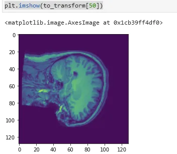
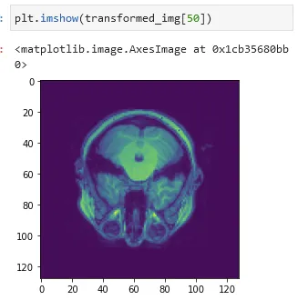
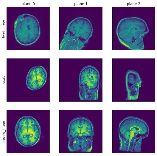
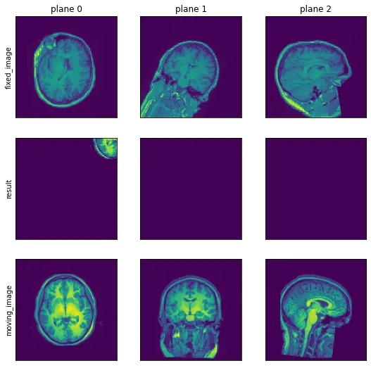
当您执行此代码时,生成的reg_monai.nii.gz应该与real_fixed.nii.gz匹配(在位置和轮廓上 - 而不是实际内容)。

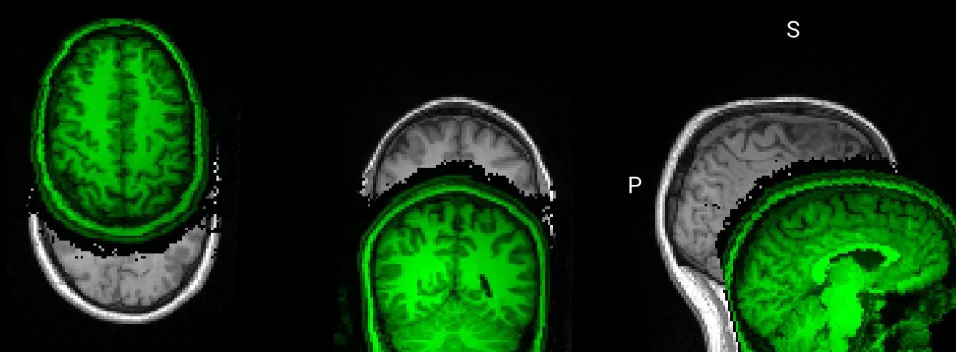
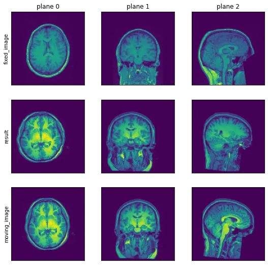
目前的结果如下所示(通过MRIcoGL查看):

coregistered images do not match

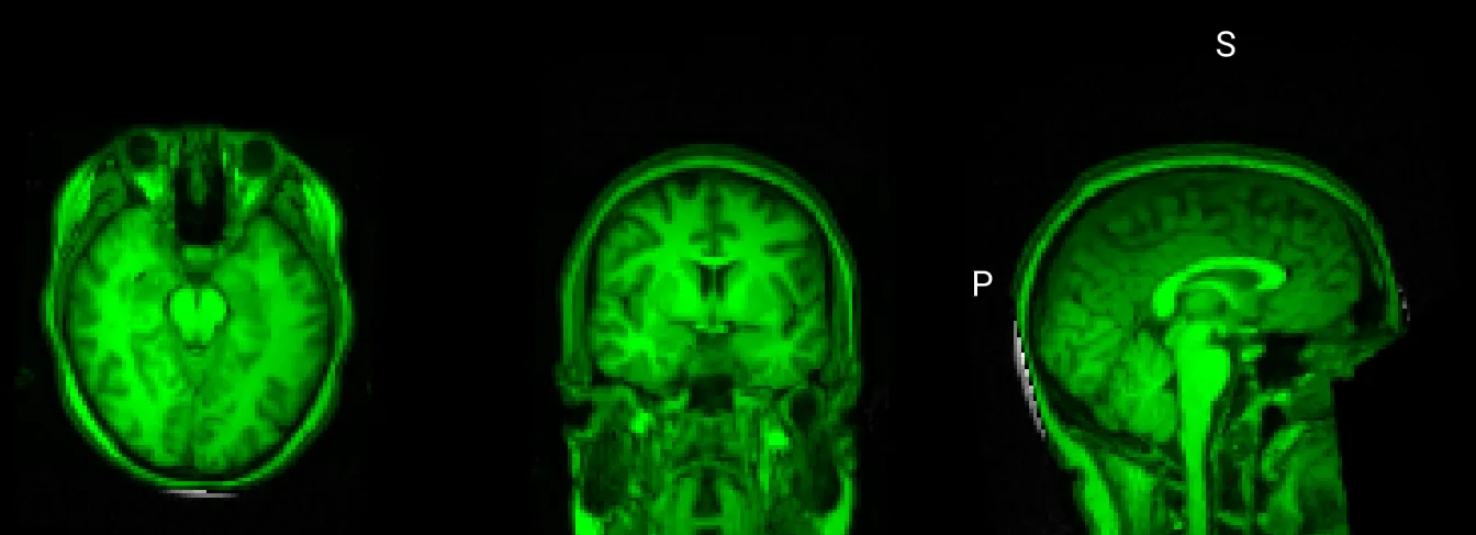
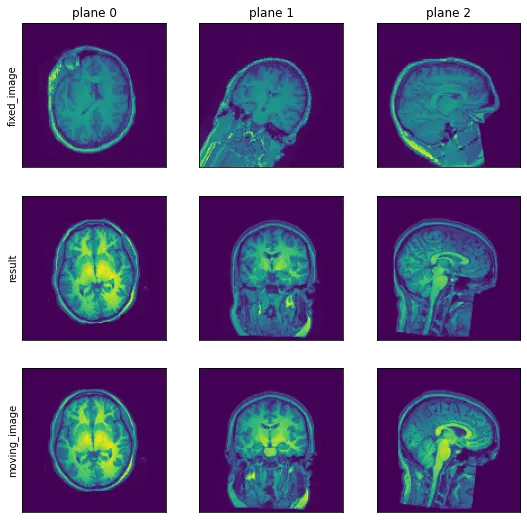
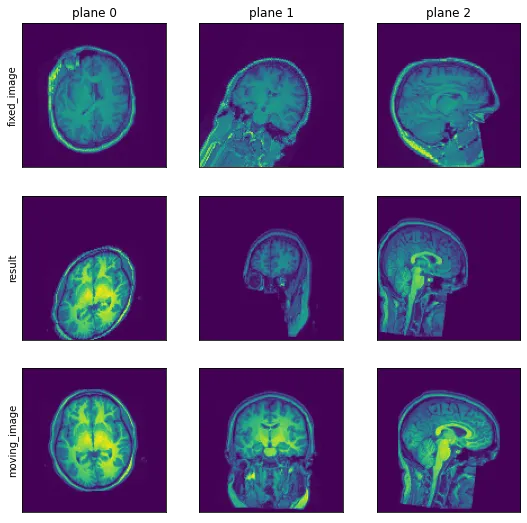
但是结果应该看起来像这样(这是直接从ITK注册输出中获取的硬编码仿射矩阵 - 这应该证明了注册已经成功,并且参数通常应该很好):

coregistered images do match


为了完整起见,这里也提供执行ITK注册并获取上述仿射矩阵的代码:
from pathlib import Path

import itk
import numpy as np

np.set_printoptions(suppress=True)  # type: ignore

folder = Path('.')

moving_image = itk.imread(str(folder / 'real_moving.nii.gz'), itk.F)
fixed_image = itk.imread(str(folder / 'real_fixed.nii.gz'), itk.F)

# Import Default Parameter Map
parameter_object = itk.ParameterObject.New()
affine_parameter_map = parameter_object.GetDefaultParameterMap('affine', 4)
affine_parameter_map['FinalBSplineInterpolationOrder'] = ['1']
affine_parameter_map['MaximumNumberOfIterations'] = ['512']
parameter_object.AddParameterMap(affine_parameter_map)

# Call registration function
result_image, result_transform_parameters = itk.elastix_registration_method(  # type: ignore
    fixed_image, moving_image, parameter_object=parameter_object)

itk.imwrite(result_image, str(folder / 'real_reg_itk.nii.gz'), compression=True)

parameter_map = result_transform_parameters.GetParameterMap(0)

rot00, rot01, rot02, rot10, rot11, rot12, rot20, rot21, rot22 = parameter_map['TransformParameters'][:9]
A = np.array([
    [rot00, rot01, rot02, 0],
    [rot10, rot11, rot12, 0],
    [rot20, rot21, rot22, 0],
    [    0,     0,     0, 1],
], dtype=float)  # yapf: disable

tx, ty, tz = parameter_map['TransformParameters'][9:]
t = np.array([
    [1, 0, 0, tx],
    [0, 1, 0, ty],
    [0, 0, 1, tz],
    [0, 0, 0,  1],
], dtype=float)  # yapf: disable

# In world coordinates
cx, cy, cz = parameter_map['CenterOfRotationPoint']
c = np.array([
    [1, 0, 0, cx],
    [0, 1, 0, cy],
    [0, 0, 1, cz],
    [0, 0, 0,  1],
], dtype=float)  # yapf: disable

ox, oy, oz = parameter_map['Origin']
o = np.array([
    [1, 0, 0, ox],
    [0, 1, 0, oy],
    [0, 0, 1, oz],
    [0, 0, 0,  1],
], dtype=float)  # yapf: disable

软件包版本:

itk-elastix==0.12.0
monai==0.8.0
nibabel==3.1.1
numpy==1.19.2

难怪你在完成甚至简单的事情时遇到麻烦。注册是在世界空间中完成的(而不是体素空间),原因是这样更容易理解。 - Dženan
2
从您提供的最小示例中理解起来有点困难,我们需要比较什么输入以及如何评估可能的输出是否正确?输出应该与fixed_image_affine相同。 - Ziur Olpa
我现在还添加了一个期望结果的示例图像和我们注意到的可能潜在问题的列表。 - Spenhouet
你是否尝试过使用 inv(c) @ t @ A @ c 而不是 c @ t @ A @ inv(c),这将得到一个方向相同但偏移了 [-2.51637511, -3.2500057, 13.11302812] 的图像。 - Bob
@Bob 不,注册系数(Atc)描述了一种将一个图像叠加到另一个图像上的变换(将“移动”图像叠加到“固定”图像上)。因此,“transform”应该以一种方式转换“移动”图像,使其在视觉上覆盖“固定”图像。这应该在空间范围内工作,因此在将变换应用于数据矩阵后,经过变换的“移动”图像具有与“固定”图像相同的仿射变换,以将两个图像映射到世界空间中。 - Spenhouet
显示剩余14条评论
2个回答

0

我猜这不是解决方案,但这个简单的代码/转换似乎让图像指向相同的方向并几乎对齐,这让我怀疑是否真的是从LPSRAS,因为这看起来是一个完全不同的坐标轴变换:

transform_matrix= np.array([
    [0, 0, 1, 0],
    [0, 1, 0, 0],
    [1, 0, 0, 0],
    [0, 0, 0,  1]], dtype=float)

to_transform: Nifti1Image = nibabel.load('file/real_moving.nii.gz')
to_transform: np.ndarray = to_transform.get_fdata() 

affine_transform = Affine(affine=transform_matrix, image_only=True,
                          mode=GridSampleMode.NEAREST, padding_mode=GridSamplePadMode.BORDER)
transformed_img = np.squeeze(affine_transform(to_transform[np.newaxis, ...])) 

另一方面,我无法在参数映射中找到正确的参数顺序(在文档中)。您确定A和t是相乘而不是相加(在t上有零对角线),也许您可以指向写有此信息的文档。
关于旋转中心,我发现了this,据我所知,这意味着:
transform = c @ transform @ c_minus

在 c 中没有对角线,无论是在 t 之前还是之后应用这个方法,我都没有答案。但对我来说,没有一个选项适用于我,因为我甚至无法使用这个数据集重现您的图像。

我在 itk-elastix 的文档中找到了一些有用的信息和 jupyter 示例 here

这是第一段代码的结果,但图像似乎与您的不同。

我给您留下了一些关于数据在我的机器上的外观的图片,包括输入、变换后的图像和参考图像。

变换前 before transformation

变换后的图像: transformed image

目标图像 目标图像

我知道这不是最终解决方案,但希望它仍然有用。


你好,你是否通过3D查看器(如MRIcoGL)查看了图像?你分享的转换矩阵对我来说没有任何意义。而且我不确定你所说的LPS和RAS方向是什么意思。更改方向实际上会导致输出图像的正确方向。我认为你混淆了*和@运算符。带有平移的@实际上执行加法。此外,你不能只取反一个矩阵 - 这就是逆矩阵的作用。但是这段代码以及你分享的链接已经在我的问题中了。 - Spenhouet
嗨!那是matplotlib,但我想那不是可视化这些东西的方式。在numpy数组中,@运算符是__matmul__矩阵乘法,乘法有很多零,看起来像是加法,但实际上不是,这个差异会使你的图像位移但不会变形,这可能就是您实际面临的情况。让我们看看parameter_map是什么,您从哪获取了参数的顺序? - Ziur Olpa
一个平移的逆运算就是在相反方向上进行平移,但是我认为使用乘法来表示逆运算也是完全正确的。 - Ziur Olpa
从查看ITK文档和代码中拼凑出了读取parameter_map的过程。前9个参数是行主序的旋转矩阵,最后3个是平移矩阵。我并不是想说这是一般情况下的加法,但在平移的情况下,它会产生相同的输出。尽管如此,我认为这里使用的是正确的操作。我正在使用4x4仿射矩阵,就像我的问题所示。这些操作与您提出的加法、减法、乘法略有不同......您是否熟悉这些? - Spenhouet
从elastix-5.0.0-manual中,您可以在第9页查看仿射变换如何定义:AffineTransform参数,您会看到一个求和而不是乘法,而您的乘法不是求和,并且它没有相同的效果,至少在Python中的意义上。 - Ziur Olpa
显示剩余3条评论

0
我看到的是图像配准过程实际上并没有起作用。
def registration_test(moving_image, fixed_image, niter=512):
  # Import Default Parameter Map
  parameter_object = itk.ParameterObject.New()
  affine_parameter_map = parameter_object.GetDefaultParameterMap('affine', 4)
  affine_parameter_map['FinalBSplineInterpolationOrder'] = ['1']
  affine_parameter_map['MaximumNumberOfIterations'] = [str(niter)]
  parameter_object.AddParameterMap(affine_parameter_map)

  # Call registration function
  result_image, result_transform_parameters = itk.elastix_registration_method(  # type: ignore
      fixed_image, moving_image, parameter_object=parameter_object)
  #transform_parameters = parameter_map['TransformParameters']
  #transform_origin = parameter_map['CenterOfRotationPoint']
  transform_parameters = result_transform_parameters.GetParameter(0, 'TransformParameters')
  transform_origin = result_transform_parameters.GetParameter(0, 'CenterOfRotationPoint')
  r = np.asarray(transform_parameters).reshape(4, 3)
  c = np.asarray(transform_origin, dtype=float)
  A = np.eye(4)
  A[:3,3] = r[3]
  A[:3,:3] = r[:3].T
  print(A, c)
  C = np.eye(4)
  C[:3, 3] = c;
  C_inv = np.eye(4)
  C_inv[:3,3] = -c;
  
  affine_transform = Affine(affine=C @ A @ C_inv,
                          image_only=True,
                          mode=GridSampleMode.NEAREST,
                          padding_mode=GridSamplePadMode.BORDER)
  
  moving_image_np = np.asarray(moving_image)
  reg_monoai = affine_transform(moving_image_np[..., np.newaxis])
  obtained = reg_monoai[..., 0]
  print(obtained.shape)
  plt.figure(figsize=(9,9))
  plt.subplot(331)
  plt.imshow(fixed_image[64,:,:], origin='lower'); plt.xticks([]); plt.yticks([])
  plt.ylabel('fixed_image'); plt.title('plane 0')
  plt.subplot(334)
  plt.imshow(obtained[64,:,:], origin='lower'); plt.xticks([]); plt.yticks([])
  plt.ylabel('result')
  plt.subplot(337)
  plt.imshow(moving_image[64,:,:], origin='lower'); plt.xticks([]); plt.yticks([])
  plt.ylabel('moving_image');
  plt.subplot(332)
  plt.imshow(fixed_image[:,64,:], origin='lower'); plt.xticks([]); plt.yticks([])
  plt.title('plane 1')
  plt.subplot(335)
  plt.imshow(obtained[:,64,:], origin='lower'); plt.xticks([]); plt.yticks([])
  plt.subplot(338)
  plt.imshow(moving_image[:,64,:], origin='lower'); plt.xticks([]); plt.yticks([])
  plt.subplot(333)
  plt.title('plane 2');
  plt.imshow(fixed_image[:,:,64], origin='lower'); plt.xticks([]); plt.yticks([])
  plt.subplot(336)
  plt.imshow(obtained[:,:,64], origin='lower'); plt.xticks([]); plt.yticks([])
  plt.subplot(339)
  plt.imshow(moving_image[:,:,64], origin='lower'); plt.xticks([]); plt.yticks([])

然后,如果我运行1000次迭代,使用您发送的非常接近的一对,这是我的结果

%%time
registration_test(moving_image, fixed_image, 1000)

[[ 1.02525991  0.01894165  0.02496272  1.02504064]
 [-0.05196394  0.93458484  0.26571434 11.92591955]
 [-0.00407657 -0.23543312  0.94091849 41.62065545]
 [ 0.          0.          0.          1.        ]] [ -0.1015625 -24.5521698   0.1015625]
(128, 128, 128)
CPU times: user 15.9 s, sys: 654 ms, total: 16.6 s
Wall time: 10.9 s

enter image description here

带有轻微旋转的测试

使用此函数绕一个轴旋转

def imrot(im, angle, axis=1):
  x,y = [i for i in range(3) if i != axis]
  A = np.eye(4)
  A[x,x] = np.cos(angle);
  A[x,y] = np.sin(angle);
  A[y,x] = -np.sin(angle);
  A[y,y] = np.cos(angle);
  f = Affine(affine=A,
        image_only=True,
        mode=GridSampleMode.NEAREST,
        padding_mode=GridSamplePadMode.BORDER)
  return itk.image_from_array(f(np.asarray(im)[np.newaxis])[0])

我发现在 10 次迭代中,moving_image 没有显著修改

%%time
e2e_test(moving_image, imrot(fixed_image, 0.5), 10)

[[ 0.9773166  -0.05882861 -0.09435328 -8.29016604]
 [ 0.01960457  1.01097845 -0.06601224 -4.62307826]
 [ 0.09305988  0.07375327  1.06381763  0.74783361]
 [ 0.          0.          0.          1.        ]] [63.5 63.5 63.5]
(128, 128, 128)
CPU times: user 3.57 s, sys: 148 ms, total: 3.71 s
Wall time: 2.24 s

enter image description here

但是,如果我将迭代次数增加到100次,与我预期的近似固定图像不同,它似乎失去了方向。

[[  1.12631932  -0.33513615  -0.70472146 -31.57349579]
 [ -0.07239085   1.08080123  -0.42268541 -28.72943354]
 [ -0.24096706  -0.08024728   0.80870164  -5.86050765]
 [  0.           0.           0.           1.        ]] [63.5 63.5 63.5]

enter image description here

经过1000次迭代

[[  1.28931626  -0.36533121  -0.52561289 -37.00919916]
 [  0.02204954   1.23661994  -0.29418401 -34.36979156]
 [ -0.32713001  -0.13135651   0.96500969   2.75931824]
 [  0.           0.           0.           1.        ]] [63.5 63.5 63.5]

enter image description here

经过10000次迭代

[[  1.46265277   0.02692694   0.14337441 -61.37788428]
 [ -0.15334478   1.37362513   0.16242297 -52.59833838]
 [ -0.53333714  -0.51411401   0.80381994  -4.97349468]
 [  0.           0.           0.           1.        ]] [63.5 63.5 63.5]

enter image description here


不,它们必须完全匹配。请参见我在问题中提供的示例图像。绿色图像完全覆盖灰色图像。灰色是固定的,绿色是变换移动的图像。 - Spenhouet
请检查我发布的结果,您这边是否出现了相同的行为? - Bob
不,我不能确认那个。对我来说注册功能很好用,你也应该可以使用。但我注意到一件事(不过那是另一个问题),就是你读取旋转矩阵的顺序是列主序而不是行主序。 - Spenhouet
如果您尝试不同数量的迭代,它是否会给您大致相同的转换? - Bob
如果在注册之前对“moving_image”应用仿射变换,结果图像是否相同?如果是这种情况,我们可以应用一组仿射变换,并从接收到的参数构建一个线性方程系统以获得预期的矩阵条目。但由于图像注册在我的端上不一致,因此您需要在您的端上运行。 - Bob

网页内容由stack overflow 提供, 点击上面的
可以查看英文原文,
原文链接