我正在尝试使用SDL 2.0函数 SDL_RenderDrawPoints() 在屏幕上绘制数据点。
在"processing.org"中,我可以使用strokeWeight()来更改我的“点”的大小。如何在SDL 2.0中实现此功能?
SDL本身不支持此功能,需要使用SDL_gfx库。
函数thicklineRGBA可以指定线条宽度。
int thickLineRGBA (SDL_Renderer *rd, Sint16 x1, Sint16 y1, Sint16 x2, Sint16 y2, Uint8 width, Uint8 r, Uint8 g, Uint8 b, Uint8 a)
int SDL_RenderSetScale(SDL_Renderer* renderer,
                   float         scaleX,
                   float         scaleY)
在使用渲染器之前,绘图坐标将按照x/y缩放因子进行缩放。这样可以使用单个坐标系统进行分辨率无关的绘图。
如果这导致渲染后端进行缩放或子像素绘制,则将使用适当的质量提示进行处理。为获得最佳效果,请使用整数缩放因子。
引自SDL Wiki
#include <SDL2/SDL.h>
#include <iostream>
int main()
{
SDL_Renderer* renderer;
SDL_Window* window;
SDL_Point points[4];
SDL_Point startingPoint;
startingPoint.x = 50;
startingPoint.y = 50;
float scale = 1.0;
if ( SDL_Init( SDL_INIT_EVERYTHING ) != 0 )
std::cout << "Failed to init SDL : " << SDL_GetError();
window = SDL_CreateWindow( "Client", 50, 50, 500, 500, 0 );
if ( window == nullptr )
std::cout << "Failed to apply video mode : " << SDL_GetError();
renderer = SDL_CreateRenderer( window, -1, SDL_RENDERER_ACCELERATED );
if ( renderer == nullptr )
std::cout << "Could not create renderer!";
SDL_RenderSetLogicalSize( renderer, 500, 500 );
// Clear background
SDL_SetRenderDrawColor( renderer, 0, 0, 0, 255 );
SDL_RenderClear( renderer );
SDL_SetRenderDrawColor( renderer, 255, 255, 255, 255 );
// Create first 4 points
points[0].x = startingPoint.x;
points[0].y = startingPoint.y;
points[1].x = startingPoint.x + 50;
points[1].y = startingPoint.y;
points[2].x = startingPoint.x;
points[2].y = startingPoint.y + 50;
points[3].x = startingPoint.x + 50;
points[3].y = startingPoint.y + 50;
SDL_RenderDrawPoints( renderer, points, 4 );
// Create seconds 4 points
startingPoint.x = 125;
scale = 2.0;
points[0].x = startingPoint.x;
points[0].y = startingPoint.y;
points[1].x = startingPoint.x + 50;
points[1].y = startingPoint.y;
points[2].x = startingPoint.x;
points[2].y = startingPoint.y + 50;
points[3].x = startingPoint.x + 50;
points[3].y = startingPoint.y + 50;
// Apply scale
for ( int i = 0; i < 4 ; ++i )
{
points[i].x /= scale;
points[i].y /= scale;
}
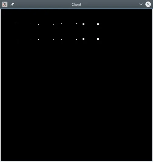
SDL_RenderSetScale( renderer, scale, scale );
SDL_RenderDrawPoints( renderer, points, 4 );
// Create third 4 points
startingPoint.x = 200;
scale = 3.0;
points[0].x = startingPoint.x;
points[0].y = startingPoint.y;
points[1].x = startingPoint.x + 50;
points[1].y = startingPoint.y;
points[2].x = startingPoint.x;
points[2].y = startingPoint.y + 50;
points[3].x = startingPoint.x + 50;
points[3].y = startingPoint.y + 50;
// Apply scale
for ( int i = 0; i < 4 ; ++i )
{
points[i].x /= scale;
points[i].y /= scale;
}
SDL_RenderSetScale( renderer, scale, scale );
SDL_RenderDrawPoints( renderer, points, 4 );
SDL_RenderPresent( renderer );
std::cin.ignore();
}
无法在评论中添加,因此以答案的形式呈现。
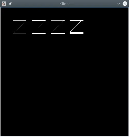
任何尝试使用@olevegard解决方案的人请注意,这仅缩放SDL_RenderDrawPoints调用 - 例如,对于对角线线条不起作用
您可以将SDL_RenderDrawPoints更改为SDL_RenderDrawLines,并查看结果,如此屏幕截图所示(我已添加了附加级别scale = 6;)