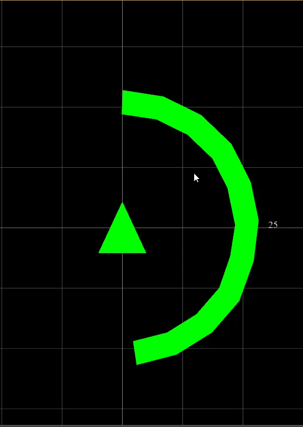
不要使用旋转来创建箭头,可以直接在原地创建箭头。同样,弯曲的管道也可以这样做。唯一需要的是由
A,B端点定义的最后一条线段。
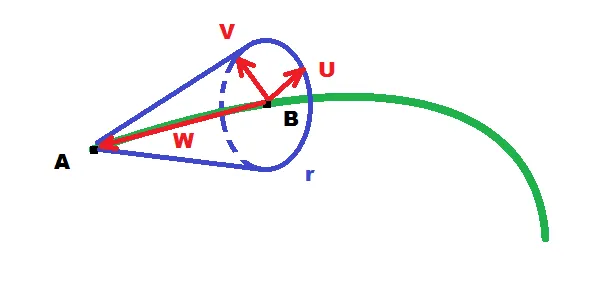
假设
A是锐利的点,
B是盘底中心。要创建箭头,您需要2个额外的基向量,称为
U,V和基础盘的半径
r。从它们可以使用简单的圆形公式创建盘点,如下所示:
obtain AB endpoints
compute U,V basis vectors
The U,V should lie in the disc base of arrowhead and should be perpendicular to each other. direction of the arrowhead (line |BA|) is the disc base normal so exploit cross product which returns perpendicular vector to the multiplied ones so:
W = B-A;
W /= |W|;    // unit vector
T = (1,0,0); // temp any non zero vector not parallel to W
if ( |(W.T)|>0.75 ) T = (0,1,0); // if abs dot product of T and W is close to 1 it means they are close to parallel so chose different T
U = (T x W) // U is perpendicular to T,W
V = (U x W) // V is perpendicular to U,W
create/render arrowhead geometry
That is easy booth A,B are centers of triangle fan (need 2) and the disc base points are computed like this:
P(ang) = B + U.r.cos(ang) + V.r.sin(ang)
So just loop ang through the whole circle with some step so you got enough points (usually 36 is enough) and do both triangle fans from them. Do not forget the last disc point must be the same as the first one otherwise you will got ugly seems or hole on the ang = 0 or 360 deg.
如果您仍然希望进行旋转,则可以按照以下方式完成。以与上述相同的方式计算出
U,V,W,并从中构建变换矩阵。原点
O将成为点
B,轴线
X,Y,Z将成为
U,V,W,顺序取决于箭头模型。
W应该与模型轴匹配。
U,V可以以任何顺序放置。因此,只需将所有向量复制到其位置,并使用此矩阵进行渲染。有关更多信息,请参见:
理解4x4齐次变换矩阵
[注]
如果您不知道如何计算向量运算(如叉积/点积或绝对值),请参见:
// cross product: W = U x V
W.x=(U.y*V.z)-(U.z*V.y)
W.y=(U.z*V.x)-(U.x*V.z)
W.z=(U.x*V.y)-(U.y*V.x)
// dot product: a = (U.V)
a=U.x*V.x+U.y*V.y+U.z*V.z
// abs of vector a = |U|
a=sqrt((U.x*U.x)+(U.y*U.y)+(U.z*U.z))
[编辑1] 简单的GL实现
我不了解你们的编程环境,但是根据下降票和评论所示,你们似乎无法自己完成这个任务,这很奇怪,因为你们已经做到了这一步。这里有一个简单的C++/GL示例,展示如何实现这个功能(你可以将其移植到你的环境中):
void glArrowRoundxy(GLfloat x0,GLfloat y0,GLfloat z0,GLfloat r,GLfloat r0,GLfloat r1,GLfloat a0,GLfloat a1,GLfloat a2)
{
const int _glCircleN=50;
const int n=3*_glCircleN;
int i,j,ix,e;
float x,y,z,x1,y1,z1,a,b,da,db=pi2/(_glCircleN-1);
float ux,uy,uz,vx,vy,vz,u,v;
GLfloat ptab[6*_glCircleN],*p0,*p1,*n0,*n1,*p;
p0=ptab+(0*_glCircleN);
p1=ptab+(3*_glCircleN);
da=+db; if (a0>a1) da=-db;
ux=0.0;
uy=0.0;
uz=1.0;
for (e=1,j=0,a=a0;e;j++,a+=da)
{
if ((da>0.0)&&(a>=a1)) { a=a1; e=0; }
if ((da<0.0)&&(a<=a1)) { a=a1; e=0; }
x1=x0+(r*cos(a));
y1=y0+(r*sin(a));
z1=z0;
vx=x1-x0;
vy=y1-y0;
vz=z1-z0;
b=sqrt((vx*vx)+(vy*vy)+(vz*vz));
if (b>1e-6) b=1.0/b; else b=0.0;
vx*=b;
vy*=b;
vz*=b;
for (ix=0,b=0.0,i=0;i<_glCircleN;i++,b+=db)
{
u=r0*cos(b);
v=r0*sin(b);
p1[ix]=x1+(ux*u)+(vx*v); ix++;
p1[ix]=y1+(uy*u)+(vy*v); ix++;
p1[ix]=z1+(uz*u)+(vz*v); ix++;
}
if (!j)
{
glBegin(GL_TRIANGLE_FAN);
glVertex3f(x1,y1,z1);
for (ix=0;ix<n;ix+=3) glVertex3fv(p1+ix);
glEnd();
}
else{
glBegin(GL_QUAD_STRIP);
for (ix=0;ix<n;ix+=3)
{
glVertex3fv(p0+ix);
glVertex3fv(p1+ix);
}
glEnd();
}
p=p0; p0=p1; p1=p;
p=n0; n0=n1; n1=p;
}
for (ix=0,b=0.0,i=0;i<_glCircleN;i++,b+=db)
{
u=r1*cos(b);
v=r1*sin(b);
p1[ix]=x1+(ux*u)+(vx*v); ix++;
p1[ix]=y1+(uy*u)+(vy*v); ix++;
p1[ix]=z1+(uz*u)+(vz*v); ix++;
}
glBegin(GL_TRIANGLE_FAN);
glVertex3f(x1,y1,z1);
for (ix=0;ix<n;ix+=3) glVertex3fv(p1+ix);
glEnd();
x1=x0+(r*cos(a2));
y1=y0+(r*sin(a2));
z1=z0;
glBegin(GL_TRIANGLE_FAN);
glVertex3f(x1,y1,z1);
for (ix=n-3;ix>=0;ix-=3) glVertex3fv(p1+ix);
glEnd();
}
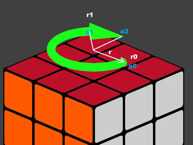
这将以中心为 x,y,z,大半径为 r 的形式在XY平面内呈现弯曲的箭头。其中r0是管道半径,r1是箭头基半径。由于我没有您的曲线定义,因此选择了XY平面上的圆。其中a0,a1,a2是箭头开始(a0),箭头头部开始(a1)和结束(a2)的角度。而pi2则是常数pi2 = 6.283185307179586476925286766559。
这个想法是记住实际和之前的管道段圆点,所以需要使用ptab,p0,p1。否则,您需要计算两次。
由于我直接选择了XY平面,因此我知道一个基向量与其垂直。第二个基向量垂直于它,并且幸运的是,圆形属性本身就提供了这一点,因此在这种情况下不需要进行叉积计算。
希望这已经足够清楚了,如果不清楚,请评论。
[编辑2]
我需要将其添加到我的引擎中,因此这是3D版本(不仅限于轴对齐箭头,锥体也会弯曲)。它与原来的代码相同,只是基向量计算方式有所改变,并且我还在标题中稍微更改了角度<a0,a1>是整个间隔,aa是箭头大小,但后者在代码中转换为原始约定。我还添加了光照计算的法线。我还添加了线性箭头,其中基向量的计算没有利用圆形属性,以防您得到不同的曲线。下面是结果:
const int _glCircleN=50;
void glCircleArrowxy(GLfloat x0,GLfloat y0,GLfloat z0,GLfloat r,GLfloat r0,GLfloat r1,GLfloat a0,GLfloat a1,GLfloat aa)
{
double pos[3]={ x0, y0, z0};
double nor[3]={0.0,0.0,1.0};
double bin[3]={1.0,0.0,0.0};
glCircleArrow3D(pos,nor,bin,r,r0,r1,a0,a1,aa);
}
void glCircleArrowyz(GLfloat x0,GLfloat y0,GLfloat z0,GLfloat r,GLfloat r0,GLfloat r1,GLfloat a0,GLfloat a1,GLfloat aa)
{
double pos[3]={ x0, y0, z0};
double nor[3]={1.0,0.0,0.0};
double bin[3]={0.0,1.0,0.0};
glCircleArrow3D(pos,nor,bin,r,r0,r1,a0,a1,aa);
}
void glCircleArrowxz(GLfloat x0,GLfloat y0,GLfloat z0,GLfloat r,GLfloat r0,GLfloat r1,GLfloat a0,GLfloat a1,GLfloat aa)
{
double pos[3]={ x0, y0, z0};
double nor[3]={0.0,1.0,0.0};
double bin[3]={0.0,0.0,1.0};
glCircleArrow3D(pos,nor,bin,r,r0,r1,a0,a1,aa);
}
void glCircleArrow3D(double *pos,double *nor,double *bin,double r,double r0,double r1,double a0,double a1,double aa)
{
int e,i,j,N=3*_glCircleN;
double U[3],V[3],u,v;
double a,b,da,db=pi2/double(_glCircleN-1),a2,rr;
double *ptab,*p0,*p1,*n0,*n1,*pp,p[3],q[3],c[3],n[3],tan[3];
ptab=new double [12*_glCircleN]; if (ptab==NULL) return;
p0=ptab+(0*_glCircleN);
n0=ptab+(3*_glCircleN);
p1=ptab+(6*_glCircleN);
n1=ptab+(9*_glCircleN);
a2=a1; da=db; aa=fabs(aa);
if (a0>a1) { da=-da; aa=-aa; }
a1-=aa;
vector_copy(U,nor);
vector_mul(tan,nor,bin);
for (e=0,j=0,a=a0;e<5;j++,a+=da)
{
if (e==0)
{
if ((da>0.0)&&(a>=a1)) { a=a1; e++; }
if ((da<0.0)&&(a<=a1)) { a=a1; e++; }
rr=r0;
}
else{
if ((da>0.0)&&(a>=a2)) { a=a2; e++; }
if ((da<0.0)&&(a<=a2)) { a=a2; e++; }
rr=r1*fabs(divide(a-a2,a2-a1));
}
u=r*cos(a);
v=r*sin(a);
vector_mul(p,bin,u);
vector_mul(q,tan,v);
vector_add(c,p, q);
vector_add(c,c,pos);
vector_sub(V,c,pos);
vector_one(V,V);
for (b=0.0,i=0;i<N;i+=3,b+=db)
{
u=cos(b);
v=sin(b);
vector_mul(p,U,u);
vector_mul(q,V,v);
vector_add(n1+i,p,q);
vector_mul(p,n1+i,rr);
vector_add(p1+i,p,c);
}
if (e>1)
{
for (i=3;i<N;i+=3)
{
vector_sub(p,p0+i ,p1+i);
vector_sub(q,p1+i-3,p1+i);
vector_mul(p,p,q);
vector_one(n1+i,p);
}
vector_sub(p,p0 ,p1);
vector_sub(q,p1+N-3,p1);
vector_mul(p,q,p);
vector_one(n1,p);
if (da>0.0) for (i=0;i<N;i+=3) vector_neg(n1+i,n1+i);
if (e== 3) for (i=0;i<N;i+=3) vector_copy(n0+i,n1+i);
}
if (!j)
{
vector_mul(n,U,V);
glBegin(GL_TRIANGLE_FAN);
glNormal3dv(n);
glVertex3dv(c);
if (da<0.0) for (i=N-3;i>=0;i-=3) glVertex3dv(p1+i);
else for (i= 0;i< N;i+=3) glVertex3dv(p1+i);
glEnd();
}
else{
glBegin(GL_QUAD_STRIP);
if (da<0.0) for (i=0;i<N;i+=3)
{
glNormal3dv(n1+i); glVertex3dv(p1+i);
glNormal3dv(n0+i); glVertex3dv(p0+i);
}
else for (i=0;i<N;i+=3)
{
glNormal3dv(n0+i); glVertex3dv(p0+i);
glNormal3dv(n1+i); glVertex3dv(p1+i);
}
glEnd();
}
pp=p0; p0=p1; p1=pp;
pp=n0; n0=n1; n1=pp;
if (e==1) a-=da;
if ((e==1)||(e==2)||(e==3)) e++;
}
delete[] ptab;
}
void glLinearArrow3D(double *pos,double *dir,double r0,double r1,double l,double al)
{
int e,i,N=3*_glCircleN;
double U[3],V[3],W[3],u,v;
double a,da=pi2/double(_glCircleN-1),r,t;
double *ptab,*p0,*p1,*n1,*pp,p[3],q[3],c[3],n[3];
ptab=new double [9*_glCircleN]; if (ptab==NULL) return;
p0=ptab+(0*_glCircleN);
p1=ptab+(3*_glCircleN);
n1=ptab+(6*_glCircleN);
vector_one(W,dir);
vector_ld(p,1.0,0.0,0.0);
vector_ld(q,0.0,1.0,0.0);
vector_ld(n,0.0,0.0,1.0);
a=fabs(vector_mul(W,p)); pp=p; t=a;
a=fabs(vector_mul(W,q)); if (t>a) { pp=q; t=a; }
a=fabs(vector_mul(W,n)); if (t>a) { pp=n; t=a; }
vector_mul(U,W,pp);
vector_mul(V,U,W);
vector_mul(U,V,W);
for (e=0;e<4;e++)
{
if (e==0) { t=0.0; r= r0; }
if (e==1) { t=l-al; r= r0; }
if (e==2) { t=l-al; r= r1; }
if (e==3) { t=l; r=0.0; }
vector_mul(c,W,t);
vector_add(c,c,pos);
for (a=0.0,i=0;i<N;i+=3,a+=da)
{
u=cos(a);
v=sin(a);
vector_mul(p,U,u);
vector_mul(q,V,v);
vector_add(n1+i,p,q);
vector_mul(p,n1+i,r);
vector_add(p1+i,p,c);
}
if (e>2)
{
for (i=3;i<N;i+=3)
{
vector_sub(p,p0+i ,p1+i);
vector_sub(q,p1+i-3,p1+i);
vector_mul(p,p,q);
vector_one(n1+i,p);
}
vector_sub(p,p0 ,p1);
vector_sub(q,p1+N-3,p1);
vector_mul(p,q,p);
vector_one(n1,p);
}
if (!e)
{
vector_neg(n,W);
glBegin(GL_TRIANGLE_FAN);
glNormal3dv(n);
glVertex3dv(c);
for (i=0;i<N;i+=3) glVertex3dv(p1+i);
glEnd();
}
else{
glBegin(GL_QUAD_STRIP);
for (i=0;i<N;i+=3)
{
glNormal3dv(n1+i);
glVertex3dv(p0+i);
glVertex3dv(p1+i);
}
glEnd();
}
pp=p0; p0=p1; p1=pp;
}
delete[] ptab;
}
用法:
glColor3f(0.5,0.5,0.5);
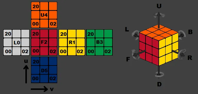
glCircleArrowyz(+3.5,0.0,0.0,0.5,0.1,0.2,0.0*deg,+270.0*deg,45.0*deg);
glCircleArrowyz(-3.5,0.0,0.0,0.5,0.1,0.2,0.0*deg,-270.0*deg,45.0*deg);
glCircleArrowxz(0.0,+3.5,0.0,0.5,0.1,0.2,0.0*deg,+270.0*deg,45.0*deg);
glCircleArrowxz(0.0,-3.5,0.0,0.5,0.1,0.2,0.0*deg,-270.0*deg,45.0*deg);
glCircleArrowxy(0.0,0.0,+3.5,0.5,0.1,0.2,0.0*deg,+270.0*deg,45.0*deg);
glCircleArrowxy(0.0,0.0,-3.5,0.5,0.1,0.2,0.0*deg,-270.0*deg,45.0*deg);
glColor3f(0.2,0.2,0.2);
glLinearArrow3D(vector_ld(+2.0,0.0,0.0),vector_ld(+1.0,0.0,0.0),0.1,0.2,2.0,0.5);
glLinearArrow3D(vector_ld(-2.0,0.0,0.0),vector_ld(-1.0,0.0,0.0),0.1,0.2,2.0,0.5);
glLinearArrow3D(vector_ld(0.0,+2.0,0.0),vector_ld(0.0,+1.0,0.0),0.1,0.2,2.0,0.5);
glLinearArrow3D(vector_ld(0.0,-2.0,0.0),vector_ld(0.0,-1.0,0.0),0.1,0.2,2.0,0.5);
glLinearArrow3D(vector_ld(0.0,0.0,+2.0),vector_ld(0.0,0.0,+1.0),0.1,0.2,2.0,0.5);
glLinearArrow3D(vector_ld(0.0,0.0,-2.0),vector_ld(0.0,0.0,-1.0),0.1,0.2,2.0,0.5);
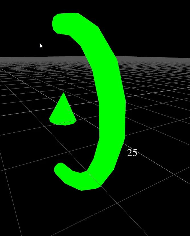
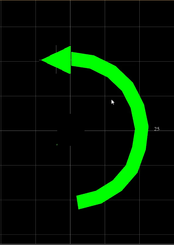
箭头概览(图片右侧):
我正在使用矢量库,以下是一些说明:
vector_mul(a[3],b[3],c[3]) 是叉积 a = b x c
vector_mul(a[3],b[3],c) 是标量乘法 a = b.c
a = vector_mul(b[3],c[3]) 是点积 a = (b.c)
vector_one(a[3],b[3]) 是单位向量 a = b/|b|
vector_copy(a[3],b[3]) 只是复制 a = b
vector_add(a[3],b[3],c[3]) 是加法 a = b + c
vector_sub(a[3],b[3],c[3]) 是减法 a = b - c
vector_neg(a[3],b[3]) 是否定 a = -b
vector_ld(a[3],x,y,z) 仅载入 a = (x,y,z)
pos 是圆形箭头的中心位置,nor 是箭头所在平面的法向量。 bin 是副法线,角度从此轴开始。应垂直于 nor。 r、r0、r1 是箭头(弯曲、管、锥)的半径。
线性箭头类似于 dir 是箭头方向,l 是箭头大小,al 是箭头尖大小。