如何使用OpenCV将PyBullet模拟坐标投影到渲染帧像素坐标?

4

我该如何将PyBullet中的对象位置转换为像素坐标,并使用PyBullet和OpenCV在帧上绘制一条线?

我们想要这样做是因为在DIRECT模式下,PyBullet本地的addUserDebugLine()函数不可用。

import pybullet as p
import numpy as np
import time
import pybullet_data
import cv2


VIDEO_RESOLUTION = (1280, 720)
MY_COLORS = [(255,0,0), (0,255,0), (0,0,255)]
def capture_frame(base_pos=[0,0,0], _cam_dist=3, _cam_yaw=45, _cam_pitch=-45):
        _render_width, _render_height = VIDEO_RESOLUTION
        view_matrix = p.computeViewMatrixFromYawPitchRoll(
            cameraTargetPosition=base_pos,
            distance=_cam_dist,
            yaw=_cam_yaw,
            pitch=_cam_pitch,
            roll=0,
            upAxisIndex=2)
        proj_matrix = p.computeProjectionMatrixFOV(
            fov=90, aspect=float(_render_width) / _render_height,
            nearVal=0.01, farVal=100.0)
        (_, _, px, _, _) = p.getCameraImage(
            width=_render_width, height=_render_height, viewMatrix=view_matrix,
            projectionMatrix=proj_matrix, renderer=p.ER_TINY_RENDERER)  # ER_BULLET_HARDWARE_OPENGL)
        rgb_array = np.array(px, dtype=np.uint8)
        rgb_array = np.reshape(rgb_array, (_render_height, _render_width, 4))
        rgb_array = rgb_array[:, :, :3]
        return rgb_array, view_matrix, proj_matrix
def render():
    frame, vmat, pmat = capture_frame()
    p1, cubeOrn = p.getBasePositionAndOrientation(1)
    p2, cubeOrn = p.getBasePositionAndOrientation(2)
    frame, view_matrix,  proj_matrix = capture_frame()
    frame = cv2.resize(frame, VIDEO_RESOLUTION)
    points = {}

    # reshape matrices
    my_order = 'C'
    pmat = np.array(proj_matrix).reshape((4,4), order=my_order)
    vmat = np.array(view_matrix).reshape((4,4), order=my_order)
    fmat = vmat.T @ pmat.T

    # compute origin from origin point in simulation
    origin = np.array([0,0,0,1])
    frame_origin = (fmat @ origin)[:3]*np.array([1280, 640, 0]) + np.array([640, 360, 0])

    # define unit vectors
    unit_vectors = [ np.array([1,0,0,1]),
                     np.array([0,1,0,1]), 
                     np.array([0,0,1,1]) ]

    for col_id, unit_vector in enumerate(unit_vectors):
        cur_point = (fmat @ unit_vector)[:3]*np.array([1280, 640, 0]) + np.array([640, 360, 0])
        cv2.line(frame, (640,360), (int(cur_point[0]),int(cur_point[1])), color=MY_COLORS[col_id], thickness=2)
    cv2.imwrite("my_rendering.jpg", frame)
    print(p1,p2)
if __name__ == '__main__':
    physicsClient = p.connect(p.DIRECT)#or p.DIRECT for non-graphical version
    p.setAdditionalSearchPath(pybullet_data.getDataPath()) #optionally
    p.setGravity(0,0,-10)
    planeId = p.loadURDF("plane.urdf")
    startPos = [1,0,0.2]
    startOrientation = p.getQuaternionFromEuler([0,0,0])
    boxId = p.loadURDF("r2d2.urdf",startPos, startOrientation)
    startPos = [0,2,0.2]
    boxId = p.loadURDF("r2d2.urdf",startPos, startOrientation)
    #set the center of mass frame (loadURDF sets base link frame) startPos/Ornp.resetBasePositionAndOrientation(boxId, startPos, startOrientation)
    for i in range (2400):
        if i == 2399:
            render()
        p.stepSimulation()


    p.disconnect()

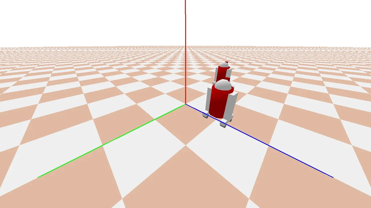
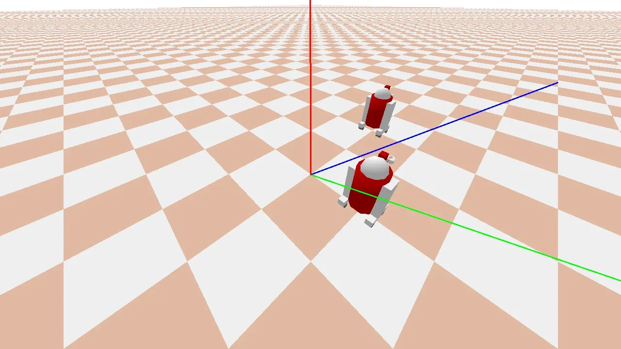
期望的输出应该是以下帧,但原点坐标框架正确绘制。例如,X、Y 和 Z 轴分别为红色、蓝色和绿色。
由于两个 R2D2 机器人分别位于 [1,0,0] 和 [0,1,0],我们可以看到坐标框架是错误的。(见下图) enter image description here 我们尝试了以下内容:
- 转置矩阵 - 不转置矩阵 - 更改计算 fmat 的顺序,例如 pmat @ vmat 而不是 vmat @ pmat 等等。
任何帮助都将不胜感激。

@S_Bersier 您是正确的,几乎就像改变纵横比会以一种cv2绘制的线条无法捕捉的方式扭曲图片。那么在这些线条上需要进行什么样的转换,以便于在绘制的坐标轴中反映出纵横比的变化呢? - avgJoe
1个回答

2

经过大量折腾,我找到了一个解决方案。尝试了一段时间后,发现只有偏航角度导致的坐标轴旋转问题还没有解决。因此,我又调用了computeViewMatrixFromYawPitchRoll函数,并使用相反的偏航角来计算坐标系的变换。不幸的是,我不确定为什么这样做有效...但它确实有效!请注意:base_pos,_cam_dist,_cam_yaw和_cam_pitch已被移动到render()中。同时,上方向也被反转了(不要问我为什么... :-))。我必须承认,这是一个非常混乱的解释...

import pybullet as p
import numpy as np
import time
import pybullet_data
import cv2
import os

VIDEO_RESOLUTION = (1280, 720)
MY_COLORS = [(255,0,0), (0,255,0), (0,0,255)]
K=np.array([[1280,0,0],[0,720,0],[0,0,1]])

def capture_frame(base_pos, _cam_dist, _cam_yaw, _cam_pitch):
        _render_width, _render_height = VIDEO_RESOLUTION
        view_matrix = p.computeViewMatrixFromYawPitchRoll(
            cameraTargetPosition=base_pos,
            distance=_cam_dist,
            yaw=_cam_yaw,
            pitch=_cam_pitch,
            roll=0,
            upAxisIndex=2)
        proj_matrix = p.computeProjectionMatrixFOV(
            fov=90, aspect=float(_render_width) / _render_height,
            nearVal=0.01, farVal=100.0)
        (_, _, px, _, _) = p.getCameraImage(
            width=_render_width, height=_render_height, viewMatrix=view_matrix,
            projectionMatrix=proj_matrix, renderer=p.ER_TINY_RENDERER)  # ER_BULLET_HARDWARE_OPENGL)
        rgb_array = np.array(px, dtype=np.uint8)
        rgb_array = np.reshape(rgb_array, (_render_height, _render_width, 4))
        rgb_array = rgb_array[:, :, :3]
        return rgb_array, view_matrix, proj_matrix
def render():
    p1, cubeOrn = p.getBasePositionAndOrientation(1)
    p2, cubeOrn = p.getBasePositionAndOrientation(2)
    base_pos=[0,0,0]
    _cam_dist=3
    _cam_yaw=45
    _cam_pitch=-30
    frame, view_matrix,  proj_matrix = capture_frame(base_pos, _cam_dist, _cam_yaw, _cam_pitch)
    frame = cv2.resize(frame, VIDEO_RESOLUTION)
    points = {}

    # inverse transform
    view_matrix = p.computeViewMatrixFromYawPitchRoll(
        cameraTargetPosition=base_pos,
        distance=_cam_dist,
        yaw=-_cam_yaw,
        pitch=_cam_pitch,
        roll=0,
        upAxisIndex=2)    
    

    my_order = 'C'
    pmat = np.array(proj_matrix).reshape((4,4), order=my_order)
    vmat = np.array(view_matrix).reshape((4,4), order=my_order)

    fmat = pmat @ vmat.T

    # compute origin from origin point in simulation
    origin = np.array([0,0,0,1])
    frame_origin = (fmat @ origin)[:3]*np.array([1280, 720, 0]) + np.array([640, 360, 0])

    # define unit vectors
    unit_vectors = [ np.array([1,0,0,1]),
                     np.array([0,1,0,1]), 
                     np.array([0,0,-1,1]) ]  

    for col_id, unit_vector in enumerate(unit_vectors):
        cur_point = (fmat @ unit_vector)[:3]*np.array([1280, 720, 0]) + np.array([640, 360, 0])
        cv2.line(frame, (640,360), (int(cur_point[0]),int(cur_point[1])), color=MY_COLORS[col_id], thickness=2)
    cv2.imwrite("my_rendering.jpg", frame)
    print(p1,p2)
if __name__ == '__main__':

    physicsClient = p.connect(p.DIRECT)#or p.DIRECT for non-graphical version
    #physicsClient = p.connect(p.GUI)#or p.DIRECT for non-graphical version
    p.setAdditionalSearchPath(pybullet_data.getDataPath()) #optionally
    p.setGravity(0,0,-10)
    planeId = p.loadURDF("plane.urdf")
    #arrows = p.loadURDF("arrows.urdf")

    startPos = [1,0,0.2]
    startOrientation = p.getQuaternionFromEuler([0,0,0])
    boxId = p.loadURDF("r2d2.urdf",startPos, startOrientation)
    startPos = [0,2,0.2]
    boxId = p.loadURDF("r2d2.urdf",startPos, startOrientation)
    #set the center of mass frame (loadURDF sets base link frame) startPos/Ornp.resetBasePositionAndOrientation(boxId, startPos, startOrientation)
    for i in range (2400):
        if i == 2399:
            render()
        p.stepSimulation()

    p.disconnect()

这是结果: 最好的问候。 这里输入图片描述

你可以通过将unit_vector定义中的np.array([0,1,0,1])替换为np.array([0,-1,0,1])来改变y轴单位向量的方向。 - S_Bersier
谢谢,这对所有分辨率都完美无缺地运行。看起来PyBullet内部的表示与OpenCV约定不符。这非常有帮助。也许有人知道表示上的差异是什么,这样我们就可以将解决方案的说明添加到其中。 - avgJoe
事实上,在pybullet提供的示例中,我找不到使用opencv的示例。尽管如此,直接使用pybullet绘制简单的线段可能是可行的。但我找不到如何做到这一点。这将是最简单的方法。 - S_Bersier
有一种方法可以通过“pybullet.addUserDebugLine”在PyBullet中添加线条,但是此方法仅在启用GUI时才有效,因此不适合我们所需的情况。 - avgJoe
另一个可能性是创建一个urdf对象(如平面),它由3个箭头/线组成,并将其添加到场景中。我也尝试过这种方法,但没有成功。 :-( - S_Bersier

网页内容由stack overflow 提供, 点击上面的
可以查看英文原文,
原文链接