在OpenGL中将纹理映射到球体上时出现了缝隙问题

13

我正在尝试在OpenGL中创建用于表示地球的几何形状。我有一个近似椭球形大地(更接近地球的椭球体)。我将地球表面的纹理映射到该几何图形上(可能是墨卡托投影或类似的投影方式)。纹理的UV坐标对应于几何的纬度和经度。但我遇到了两个问题,目前无法解决。我使用的是OpenSceneGraph,但我认为这是普遍的OpenGL / 3D编程问题。

  • 存在非常明显的纹理接缝。我确定这是因为我不知道如何将UV坐标映射到出现接缝的XYZ坐标。我仅将UV坐标映射到绕过最后一个顶点之前...你需要将两个不同的UV坐标映射到同一个XYZ顶点以消除接缝。是否有一种通常使用的技巧来解决这个问题,还是我做错了什么?

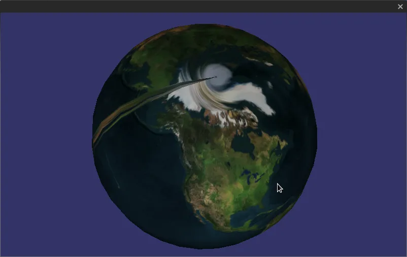
  • 在极点处发生了疯狂的旋转畸变。我猜测这是因为我将单个UV点映射到了极点(对于地球,我使用[0.5,1]表示北极,[0.5,0]表示南极)。还有其他的方法吗?我可以接受这种畸变...但在低分辨率网格上非常明显。

我附加了一张图片以说明我的问题。

I suck at rendering Earth


2
你能分享一下你是如何生成UV坐标的,以及你使用的纹理对象的方法吗? - Andrew Khosravian
OpenGL ES通用版本教程:https://dev59.com/okXRa4cB1Zd3GeqPvN_z 相关问题请参见:https://dev59.com/yHTYa4cB1Zd3GeqPrB82 - Ciro Santilli OurBigBook.com
6个回答

8
一般处理方式是使用一个立方体贴图,而非2D纹理。
但如果您坚持使用2D纹理,则必须在网格拓扑中创建一个断点。之所以会出现那条经线,是因为您有一个顶点的纹理坐标大约为0.9,而其相邻的顶点的纹理坐标为0.0。实际上,您需要的是0.9的那个相邻于1.0的纹理坐标。
这样做意味着将位置复制到球体的一行中。因此,您的数据中使用了相同的位置两次。其中一个与纹理坐标1.0相关联,并且与0.9的纹理坐标相邻。另一个具有纹理坐标0.0,并且与0.1的顶点相邻。
从拓扑上讲,您需要在球体上切下一条经线。

那太糟糕了。感谢你提醒我。作为一个快速的跟进,你有关于在球体上实现立方体贴图的资源吗? - Prismatic
@Pris:对于球体来说,立方体贴图是微不足道的。你可以直接将顶点位置(或法线)作为纹理坐标输入到立方体贴图中。立方体贴图本身由6个正方形组成,排列成一个立方体。纹理坐标确定了从立方体中心的方向,与立方体本身的交点产生了纹素。 - datenwolf

2

你的链接真的帮了我很多,furqan,谢谢。
为什么你不能弄明白呢?我一度陷入困境的地方是,我不知道在计算纹理坐标时可以超出[0,1]区间。这使得用OpenGL跳过纹理的一侧变得更容易,在OpenGL进行所有插值而无需计算纹理实际结束位置的情况下。


这非常有帮助。谢谢!真的是一个简单而优雅的解决方案! - Sibbs Gambling

1
你还可以采用一种不太规范的方法:在顶点着色器和片元着色器之间插值X、Y位置,并在片元着色器中重新计算正确的纹理坐标。这可能会稍微慢一些,但它不涉及重复顶点,而且我认为更简单。
例如:
顶点着色器:
#version 150 core
uniform mat4 projM;
uniform mat4 viewM;
uniform mat4 modelM;
in vec4 in_Position;
in vec2 in_TextureCoord;
out vec2 pass_TextureCoord;
out vec2 pass_xy_position;
void main(void) {
    gl_Position = projM * viewM * modelM * in_Position;
    pass_xy_position = in_Position.xy; // 2d spinning interpolates good!
    pass_TextureCoord = in_TextureCoord;
}

片元着色器:
#version 150 core
uniform sampler2D texture1;
in vec2 pass_xy_position;
in vec2 pass_TextureCoord;
out vec4 out_Color;

#define PI 3.141592653589793238462643383279

void main(void) {
    vec2 tc = pass_TextureCoord;
    tc.x = (PI + atan(pass_xy_position.y, pass_xy_position.x)) / (2 * PI); // calculate angle and map it to 0..1
    out_Color = texture(texture1, tc);
}

1

花了很长时间才解决这个非常烦人的问题。我在Unity中使用C#进行编程,不想复制任何顶点。(会导致我的概念未来出现问题)所以我采用了着色器的想法,效果还不错。虽然我相信代码可能需要进行重度优化,但我必须想出如何将其从这个地方移植到CG中,但它起作用了。这是给其他遇到相同问题的人提供的,就像我一样,在寻找解决方案时偶然看到了这篇文章。

    Shader "Custom/isoshader" {
Properties {
        decal ("Base (RGB)", 2D) = "white" {}
    }
    SubShader {
        Pass {
        Fog { Mode Off }

        CGPROGRAM

        #pragma vertex vert
        #pragma fragment frag
        #define PI 3.141592653589793238462643383279

        sampler2D decal;

        struct appdata {
            float4 vertex : POSITION;
            float4 texcoord : TEXCOORD0;
        };

        struct v2f {
            float4 pos : SV_POSITION;
            float4 tex : TEXCOORD0;
            float3 pass_xy_position : TEXCOORD1;
        };

        v2f vert(appdata v){
            v2f  o;
            o.pos = mul(UNITY_MATRIX_MVP, v.vertex);
            o.pass_xy_position = v.vertex.xyz;
            o.tex = v.texcoord;
            return o;
        }

        float4 frag(v2f i) : COLOR {
            float3 tc = i.tex;
            tc.x = (PI + atan2(i.pass_xy_position.x, i.pass_xy_position.z)) / (2 * PI);
            float4 color = tex2D(decal, tc);
            return color;
        }

        ENDCG
    }
}

}


我建议使用normal而不是position,以防您的球体网格不是直径为1且原点为0,0,0。 - jjxtra

0
一种方法就像在被接受的答案中所述。在生成顶点属性数组的代码中,您将有如下代码:
// FOR EVERY TRIANGLE
const float threshold = 0.7;
if(tcoords_1.s > threshold || tcoords_2.s > threshold || tcoords_3.s > threshold)
{
    if(tcoords_1.s < 1. - threshold)
    {
        tcoords_1.s += 1.;
    }
    if(tcoords_2.s < 1. - threshold)
    {
        tcoords_2.s += 1.;
    }
    if(tcoords_3.s < 1. - threshold)
    {
        tcoords_3.s += 1.;
    }
}

如果您有未沿子午线对齐的三角形,您还需要使用glTexParameteri(GL_TEXTURE_2D, GL_TEXTURE_WRAP_S, GL_REPEAT); 。您也需要使用glDrawArrays,因为具有相同位置的顶点将具有不同的纹理坐标。

我认为更好的方法是消除所有罪恶之根,在这种情况下是纹理坐标插值。由于您基本上了解您的球体/椭球体的全部信息,因此可以在片元着色器中根据位置计算纹理坐标、法线等。这意味着生成顶点属性的CPU代码将简单得多,您可以再次使用索引绘图。我认为这种方法并不脏。它很干净。


0
正如Nicol Bolas所说,一些三角形的UV坐标从0.9左右回到了0,因此插值会在接缝处弄乱纹理。在我的代码中,我创建了这个函数来复制接缝周围的顶点。这将创建一个锋利的线条将那些顶点分开。如果您的纹理在接缝周围只有水(太平洋?),您可能不会注意到这条线。希望它能有所帮助。
/**
 *  After spherical projection, some triangles have vertices with
 *  UV coordinates that are far away (0 to 1), because the Azimuth
 *  at 2*pi = 0. Interpolating between 0 to 1 creates artifacts
 *  around that seam (the whole texture is thinly repeated at
 *  the triangles around the seam).
 *  This function duplicates vertices around the seam to avoid
 *  these artifacts.
 */
void PlatonicSolid::SubdivideAzimuthSeam() {
    if (m_texCoord == NULL) {
        ApplySphericalProjection();
    }

    // to take note of the trianges in the seam
    int facesSeam[m_numFaces];

    // check all triangles, looking for triangles with vertices
    // separated ~2π. First count.
    int nSeam = 0;
    for (int i=0;i < m_numFaces; ++i) {
        // check the 3 vertices of the triangle
        int a = m_faces[3*i];
        int b = m_faces[3*i+1];
        int c = m_faces[3*i+2];
        // just check the seam in the azimuth
        float ua = m_texCoord[2*a];
        float ub = m_texCoord[2*b];
        float uc = m_texCoord[2*c];
        if (fabsf(ua-ub)>0.5f || fabsf(ua-uc)>0.5f || fabsf(ub-uc)>0.5f) {
            //test::printValue("Face: ", i, "\n");
            facesSeam[nSeam] = i;
            ++nSeam;
        }
    }

    if (nSeam==0) {
        // no changes
        return;
    }

    // reserve more memory
    int nVertex = m_numVertices;
    m_numVertices += nSeam;
    m_vertices = (float*)realloc((void*)m_vertices, 3*m_numVertices*sizeof(float));
    m_texCoord = (float*)realloc((void*)m_texCoord, 2*m_numVertices*sizeof(float));

    // now duplicate vertices in the seam
    // (the number of triangles/faces is the same)
    for (int i=0; i < nSeam; ++i, ++nVertex) {
        int t = facesSeam[i]; // triangle index
        // check the 3 vertices of the triangle
        int a = m_faces[3*t];
        int b = m_faces[3*t+1];
        int c = m_faces[3*t+2];
        // just check the seam in the azimuth
        float u_ab = fabsf(m_texCoord[2*a] - m_texCoord[2*b]);
        float u_ac = fabsf(m_texCoord[2*a] - m_texCoord[2*c]);
        float u_bc = fabsf(m_texCoord[2*b] - m_texCoord[2*c]);
        // select the vertex further away from the other 2
        int f = 2;
        if (u_ab >= 0.5f && u_ac >= 0.5f) {
            c = a;
            f = 0;
        } else if (u_ab >= 0.5f && u_bc >= 0.5f) {
            c = b;
            f = 1;
        }

        m_vertices[3*nVertex] = m_vertices[3*c];      // x
        m_vertices[3*nVertex+1] = m_vertices[3*c+1];  // y
        m_vertices[3*nVertex+2] = m_vertices[3*c+2];  // z
        // repeat u from texcoord
        m_texCoord[2*nVertex] = 1.0f - m_texCoord[2*c];
        m_texCoord[2*nVertex+1] = m_texCoord[2*c+1];
        // change this face so all the vertices have close UV
        m_faces[3*t+f] = nVertex;
    }

}

网页内容由stack overflow 提供, 点击上面的
可以查看英文原文,
原文链接