使用Opencv检测图像中矩形的中心和角度

15

我有一张如下的图片:

包含许多矩形轮廓的示例图像

我需要找出矩形的数量,每个矩形的中心以及通过中心并且平行于矩形长边的轴线与水平方向的逆时针夹角。我已经找到了图像中矩形的数量,但在寻找中心和反射角度方面遇到了困难。使用矩能量法计算中心点并不能给出正确的答案。

我的代码:

import cv2
import numpy as np 
import sys

img = cv2.imread(str(sys.argv[1]),0)
ret,thresh = cv2.threshold(img,127,255,0)
contours,hierarchy = cv2.findContours(thresh,1,2)


for contour in contours:
    area = cv2.contourArea(contour)
    if area>100000:
        contours.remove(contour)


cnt = contours[0]

epsilon = 0.02*cv2.arcLength(cnt,True)
approx = cv2.approxPolyDP(cnt,epsilon,True)

print 'No of rectangles',len(approx)


#finding the centre of the contour
M = cv2.moments(cnt)

cx = int(M['m10']/M['m00'])
cy = int(M['m01']/M['m00'])

print cx,cy

3
使用findContours函数提取轮廓,并使用minAreaRect函数计算旋转矩形。 - Micka
请查看我的答案,这里有@Micka指出的方法的C++实现示例:链接 - sturkmen
2
对于矩形,Micka的解决方案是最优的,作为更一般的情况,您还可以查看基于PCA的方法:http://docs.opencv.org/master/d1/dee/tutorial_introduction_to_pca.html#gsc.tab=0 - Andrey Smorodov
@Micka,您能详细说明一下minAreaRect吗?它如何帮助找到逆时针方向相对于水平线的角度?如果我使用moments,为什么无法得到轮廓的中心点? - Kaushik Ramachandran
3个回答

22
这是使用OpenCV的minAreaRect函数的方法。它是用C++编写的,但你可能很容易适应,因为几乎只使用了OpenCV函数。
cv::Mat input = cv::imread("../inputData/rectangles.png");

cv::Mat gray;
cv::cvtColor(input,gray,CV_BGR2GRAY);

// since your image has compression artifacts, we have to threshold the image
int threshold = 200;
cv::Mat mask = gray > threshold;

cv::imshow("mask", mask);
// extract contours
std::vector<std::vector<cv::Point> > contours;
cv::findContours(mask, contours, CV_RETR_EXTERNAL, CV_CHAIN_APPROX_NONE);

for(int i=0; i<contours.size(); ++i)
{
    // fit bounding rectangle around contour
    cv::RotatedRect rotatedRect = cv::minAreaRect(contours[i]);

    // read points and angle
    cv::Point2f rect_points[4]; 
    rotatedRect.points( rect_points );

    float  angle = rotatedRect.angle; // angle

    // read center of rotated rect
    cv::Point2f center = rotatedRect.center; // center

    // draw rotated rect
    for(unsigned int j=0; j<4; ++j)
        cv::line(input, rect_points[j], rect_points[(j+1)%4], cv::Scalar(0,255,0));

    // draw center and print text
    std::stringstream ss;   ss << angle; // convert float to string
    cv::circle(input, center, 5, cv::Scalar(0,255,0)); // draw center
    cv::putText(input, ss.str(), center + cv::Point2f(-25,25), cv::FONT_HERSHEY_COMPLEX_SMALL, 1, cv::Scalar(255,0,255)); // print angle
}

导致了这张图片的产生:

enter image description here

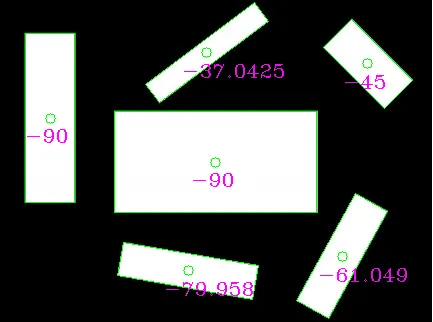
如你所见,角度可能不是你想要的(因为它们随机使用较长或较短的线作为参考)。 相反,你可以提取矩形的较长边并手动计算角度。
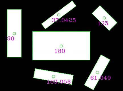
如果你选择旋转矩形的较长边并从中计算角度,结果会是这样的:
// choose the longer edge of the rotated rect to compute the angle
cv::Point2f edge1 = cv::Vec2f(rect_points[1].x, rect_points[1].y) - cv::Vec2f(rect_points[0].x, rect_points[0].y);
cv::Point2f edge2 = cv::Vec2f(rect_points[2].x, rect_points[2].y) - cv::Vec2f(rect_points[1].x, rect_points[1].y);

cv::Point2f usedEdge = edge1;
if(cv::norm(edge2) > cv::norm(edge1))
{
    usedEdge = edge2;
}

cv::Point2f reference = cv::Vec2f(1,0); // horizontal edge

angle = 180.0f/CV_PI * acos((reference.x*usedEdge.x + reference.y*usedEdge.y) / (cv::norm(reference) *cv::norm(usedEdge)));

给出这个结果,应该是你在寻找的!

enter image description here

编辑:看起来楼主没有使用他发布的输入图像,因为参考矩形的中心会落在图像之外。
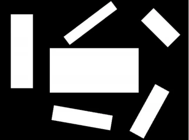
使用这个输入(手动重新缩放但可能仍不是最佳选择):

enter image description here

我得到了这些结果(蓝点是由操作提供的参考矩形中心):
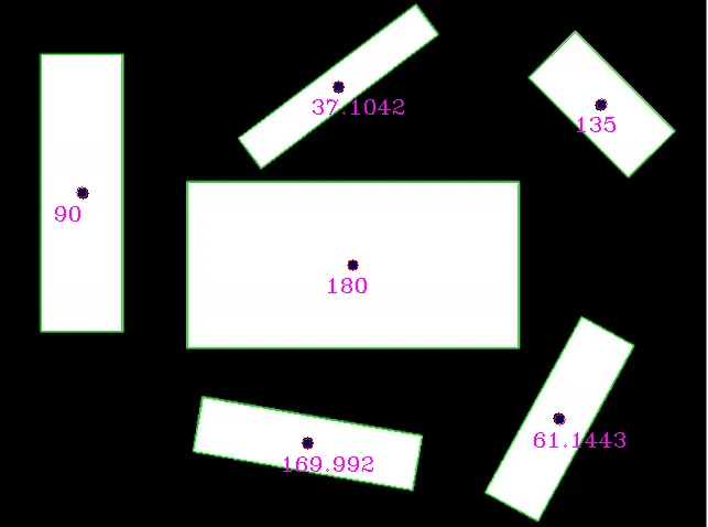
enter image description here

与检测结果进行比较:
reference (x,y,angle)    detection (x,y,angle)
(320,240,0)              (320, 240, 180) // angle 180 is equal to angle 0 for lines
(75,175,90)              (73.5, 174.5, 90)
(279,401,170)            (279.002, 401.824, 169.992)
(507,379,61)             (507.842, 379.75, 61.1443)
(545,95,135)             (545.75, 94.25, 135)
(307,79,37)              (306.756, 77.8384, 37.1042)

我很想看到真正的输入图像,也许结果会更好。

更新的代码和结果。这很简单。如果有帮助,请随意点赞。 - Micka
我对 moments 没有太多经验。对于轮廓提取,您应该尝试使用表示轮廓密集的标志。 - Micka
我已经尝试了所有可用的标志,轮廓检测部分没有问题。我已经遮盖了轮廓并逐个进行了测试。但是我对矩形中心的瞬间/最小面积矩形给出的答案有些担心。为什么会给我错误的答案? - Kaushik Ramachandran
请问您能发布minAreaRect的中心/角度输出吗?在视觉上评估,中心点非常好。 - Micka
1
非常感谢你,Micka。这个解决方案救了我的一天。这是一个向正确方向的转折点。我曾经找到了文档的平均旋转角度,计算所有(重要)角度的加权平均值。这是核心。我只需要在 C# 中删除更多噪音。 - Marco Mangia
显示剩余5条评论

2

以下是如何完成此操作的步骤:

  1. 使用连通组件标记来检测每个模式(在您的情况下为矩形)。
  2. 将模式分别放在不同的图像中。
  3. (可选)如果模式不全是矩形,则使用形状指数来区分它们。
  4. 使用主成分分析(PCA)计算主轴,这将给出您要查找的角度。

3
您可以使用代码片段来改进答案。另外,由于这里只有矩形,因此“minAreaRect”就足够了。 - Miki

1

approx = cv2.approxPolyDP(cnt,epsilon,True) 创建给定闭合轮廓的近似多边形。多边形中的线段长度可变,导致错误的矩计算,因为它期望从规则网格中采样点以给出正确的中心。

有三种解决方案:

  1. 在调用多边形逼近方法之前使用原始轮廓的矩。
  2. 使用 drawContours 生成每个封闭轮廓内部区域的掩码,然后使用生成的掩码的矩来计算中心。
  3. 沿着封闭多边形的每条线段以单位距离采样点,并使用生成的点集来自行计算矩。这应该会给你相同的中心。

网页内容由stack overflow 提供, 点击上面的
可以查看英文原文,
原文链接