由于您的假设参考点和目标点在(大约)同一平面上。,您可以应用所描述的“算法1:平面测量”方法。
Antonio Criminisi。“单视图计量:算法和应用(特邀论文)”。在:Pattern Recognition。Luc Van Gool编辑。第2449卷。计算机科学讲义。Springer Berlin Heidelberg,2002年,第224-239页。
该方法允许您测量位于同一平面上的两个点之间的距离。
基本上
P=H*p (1)
其中p是以齐次坐标表示的图像中的点,P是对应的以齐次坐标表示的三维世界平面上的点,H是一个称为单应矩阵的3x3矩阵,*表示矩阵向量乘法。
    h11 h12 h13
H = h21 h22 h23
    h31 h32 h33
p的度量单位为像素,例如,如果
p是位于行
r和列
c的点,则表示为
[r,c,1]。
P的度量单位是您的世界单位,例如米,您可以假设您的三维世界平面为平面
Z=0,因此
P表示为齐次向量
[X,Y,1]。
因此,“算法1:平面测量”的一点修改如下:
- 给定平面表面的图像,估计图像到世界的单应矩阵H。假设H的9个元素无量纲。
- 在图像中选择两个属于参考物体的点p1=[r1,c1,1]和p2=[r2,c2,1]。
- 通过(1)将每个图像点反投影到世界平面上,以获得两个世界点P1和P2。你需要进行矩阵-向量乘法,然后你需要将结果向量除以其第三个分量,以获得齐次向量。例如,P1=[X1,Y1,1]是P1=[(c1*h_12 + h_11*r1 + h_13)/(c1*h_32 + h_31*r1 + h_33),(c1*h_22 + h_21*r1 + h_23)/(c1*h_32 + h_31*r1 + h_33),1]。假设暂时假设H的九个元素是无量纲的,这意味着X1、Y1、X2和Y2的度量单位为像素。
- 计算P1和P2之间的距离R,即R=sqrt(pow(X1-X2,2)+pow(Y1-Y2,2)),R仍以像素表示。现在,由于P1和P2位于参考物体上,这意味着您知道它们之间的距离(以米为单位),让我们称其为距离M。
- 计算比例因子s,s=M/R,s的尺寸为每像素米。
- 将H的每个元素乘以s,并称得到的新矩阵为G。现在,G的元素以米每像素表示。
- 现在,在图像中选择两个属于目标物体的点p3和p4。
- 通过G反向投影p3和p4,以获得P3和P4。P3=G*p3和P4=G*p4。再次将每个向量除以其第三个元素。P3=[X3,Y3,1]和P4=[X4,Y4,1],现在X3、Y3、X4和Y4以米为单位。
- 计算所需目标距离D,即D=sqrt(pow(X3-X4,2)+pow(Y3-Y4,2))。D现在以米为单位。
上述论文的附录解释了如何计算
H,或者您可以使用OpenCV
cv::findHomography:基本上,您需要至少四个对应点,这些点在现实世界中和图像中。
另一个关于如何估计
H的信息来源在:
JOHNSON, Micah K.; FARID, Hany. Metric measurements on a plane from a single image. Dept. Comput. Sci., Dartmouth College, Tech. Rep. TR2006-579, 2006.
如果您还需要估计测量的准确性,可以在以下详细信息中找到:
A. Criminisi.
Accurate Visual Metrology from Single and Multiple Uncalibrated Images. Distinguished Dissertation Series. Springer-Verlag London Ltd., Sep 2001. ISBN: 1852334681.
使用OpenCV的C++示例:
#include "opencv2/core/core.hpp"
#include "opencv2/imgproc/imgproc.hpp"
#include "opencv2/highgui/highgui.hpp"
#include "opencv2/calib3d/calib3d.hpp"
void to_homogeneous(const std::vector< cv::Point2f >& non_homogeneous, std::vector< cv::Point3f >& homogeneous )
{
homogeneous.resize(non_homogeneous.size());
for ( size_t i = 0; i < non_homogeneous.size(); i++ ) {
homogeneous[i].x = non_homogeneous[i].x;
homogeneous[i].y = non_homogeneous[i].y;
homogeneous[i].z = 1.0;
}
}
void from_homogeneous(const std::vector< cv::Point3f >& homogeneous, std::vector< cv::Point2f >& non_homogeneous )
{
non_homogeneous.resize(homogeneous.size());
for ( size_t i = 0; i < non_homogeneous.size(); i++ ) {
non_homogeneous[i].x = homogeneous[i].x / homogeneous[i].z;
non_homogeneous[i].y = homogeneous[i].y / homogeneous[i].z;
}
}
void draw_cross(cv::Mat &img, const cv::Point center, float arm_length, const cv::Scalar &color, int thickness = 5 )
{
cv::Point N(center - cv::Point(0, arm_length));
cv::Point S(center + cv::Point(0, arm_length));
cv::Point E(center + cv::Point(arm_length, 0));
cv::Point W(center - cv::Point(arm_length, 0));
cv::line(img, N, S, color, thickness);
cv::line(img, E, W, color, thickness);
}
double measure_distance(const cv::Point2f& p1, const cv::Point2f& p2, const cv::Matx33f& GG)
{
std::vector< cv::Point2f > ticks(2);
ticks[0] = p1;
ticks[1] = p2;
std::vector< cv::Point3f > ticks_h;
to_homogeneous(ticks, ticks_h);
std::vector< cv::Point3f > world_ticks_h(2);
for ( size_t i = 0; i < ticks_h.size(); i++ ) {
world_ticks_h[i] = GG * ticks_h[i];
}
std::vector< cv::Point2f > world_ticks_back;
from_homogeneous(world_ticks_h, world_ticks_back);
return cv::norm(world_ticks_back[0] - world_ticks_back[1]);
}
int main(int, char**)
{
cv::Mat img = cv::imread("single-view-metrology.JPG");
std::vector< cv::Point2f > world_tenth_of_mm;
std::vector< cv::Point2f > img_px;
cv::Point2f TL(711, 64);
cv::Point2f BL(317, 1429);
cv::Point2f TR(1970, 175);
cv::Point2f BR(1863, 1561);
const int A4_w_mm = 210;
const int A4_h_mm = 297;
const int scale = 10;
img_px.push_back(TL);
world_tenth_of_mm.push_back(cv::Point2f(0.0, 0.0));
img_px.push_back(TR);
world_tenth_of_mm.push_back(cv::Point2f(A4_w_mm * scale, 0.0));
img_px.push_back(BL);
world_tenth_of_mm.push_back(cv::Point2f(0.0, A4_h_mm * scale));
img_px.push_back(BR);
world_tenth_of_mm.push_back(cv::Point2f(A4_w_mm * scale, A4_h_mm * scale));
cv::Mat H = cv::findHomography(world_tenth_of_mm, img_px);
cv::Mat G = H.inv();
cv::Mat warped;
cv::warpPerspective(img, warped, G, cv::Size(2600, 2200 * 297 / 210));
{
cv::Point2f tick_0(2017, 1159);
cv::Point2f tick_1(1949, 1143);
std::ostringstream oss;
oss << measure_distance(tick_0, tick_1, G) / scale;
cv::line(img, tick_0, tick_1, CV_RGB(0, 255, 0));
cv::putText(img, oss.str(), (tick_0 + tick_1) / 2, cv::FONT_HERSHEY_PLAIN, 3, CV_RGB(0, 255, 0), 3);
}
{
cv::Point2f tick_11(1277, 988);
cv::Point2f tick_12(1211, 973);
std::ostringstream oss;
oss << measure_distance(tick_11, tick_12, G) / scale;
cv::line(img, tick_11, tick_12, CV_RGB(0, 255, 0));
cv::putText(img, oss.str(), (tick_11 + tick_12) / 2, cv::FONT_HERSHEY_PLAIN, 3, CV_RGB(0, 255, 0), 3);
}
draw_cross(img, TL, 40, CV_RGB(255, 0, 0));
draw_cross(img, TR, 40, CV_RGB(255, 0, 0));
draw_cross(img, BL, 40, CV_RGB(255, 0, 0));
draw_cross(img, BR, 40, CV_RGB(255, 0, 0));
cv::namedWindow( "Input image", cv::WINDOW_NORMAL );
cv::imshow( "Input image", img );
cv::imwrite("img.png", img);
cv::namedWindow( "Rectified image", cv::WINDOW_NORMAL );
cv::imshow( "Rectified image", warped );
cv::imwrite("warped.png", warped);
cv::waitKey(0);
return 0;
}
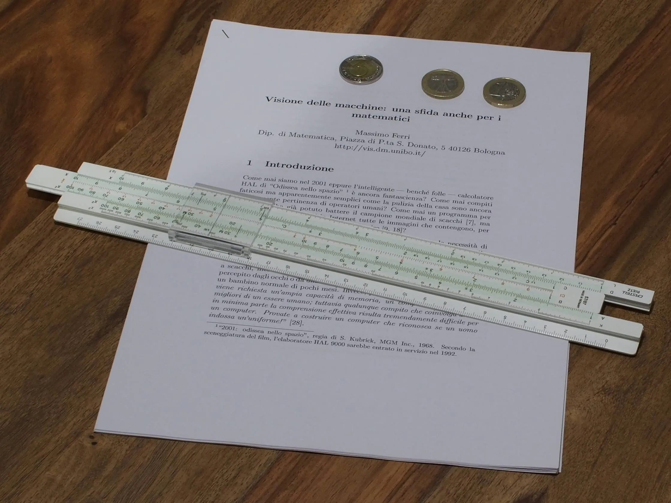
输入图像,此处您的参考对象是A4纸张,目标对象是滑尺:
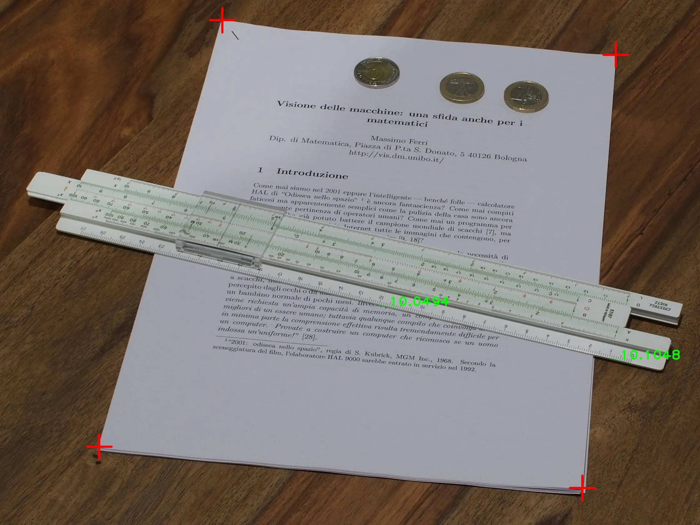
带有测量值的输入图像,红色十字用于估计单应性:
矫正后的图像:
