我正在尝试在GLSL中编写正确的二维仿射纹理映射。
解释:
解释:
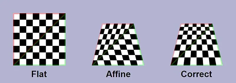
我不需要这些图片中的任何一张。正确的那张(标为Correct)进行了透视校正,而我不想要这个。因此,这个解决方案:了解Q纹理坐标(没有更多改进)不是我要找的。
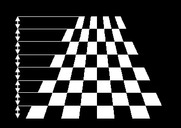
我只想简单地“拉伸”四边形内部的纹理,就像这样:
我不需要这些图片中的任何一张。正确的那张(标为Correct)进行了透视校正,而我不想要这个。因此,这个解决方案:了解Q纹理坐标(没有更多改进)不是我要找的。
我只想简单地“拉伸”四边形内部的纹理,就像这样:
varying vec2 shiftedPosition, width_height;

#ifdef VERTEX
void main() {
    gl_Position = gl_ModelViewProjectionMatrix * gl_Vertex;
    shiftedPosition = gl_MultiTexCoord0.xy; // left and bottom edges zeroed.
    width_height = gl_MultiTexCoord1.xy;
}
#endif

#ifdef FRAGMENT
uniform sampler2D _MainTex;
void main() {
    gl_FragColor = texture2D(_MainTex, shiftedPosition / width_height);
}
#endif
C#:
// Zero out the left and bottom edges,
// leaving a right trapezoid with two sides on the axes and a vertex at the origin.
var shiftedPositions = new Vector2[] {
    Vector2.zero,
    new Vector2(0, vertices[1].y - vertices[0].y),
    new Vector2(vertices[2].x - vertices[1].x, vertices[2].y - vertices[3].y),
    new Vector2(vertices[3].x - vertices[0].x, 0)
};
mesh.uv = shiftedPositions;

var widths_heights = new Vector2[4];
widths_heights[0].x = widths_heights[3].x = shiftedPositions[3].x;
widths_heights[1].x = widths_heights[2].x = shiftedPositions[2].x;
widths_heights[0].y = widths_heights[1].y = shiftedPositions[1].y;
widths_heights[2].y = widths_heights[3].y = shiftedPositions[2].y;
mesh.uv2 = widths_heights;
vertices = [Vec2(-1, -1), Vec2(-0.5, 1), Vec2(0.5, 1), Vec2(1, -1)],shiftedPositions = [Vec2(0, 0), Vec2(0, 2), Vec2(1, 2), Vec2(2, 0)]和width_heights = [Vec2(2, 2), Vec2(1, 2), Vec2(1, 2), Vec2(2, 2)]。我的片段代码如下:gl_FragColor = texture2D(colormap, gl_TexCoord[0].xy / width_heights.xy);(我必须使用gl_TexCoord)。但是它根本不起作用。 - velkyel如果还有人感兴趣,这里提供一个C#实现,它接受由顺时针屏幕顶点 (x0,y0) (x1,y1) ... (x3,y3) 定义的四边形以及一个任意像素点 (x,y),并计算该像素点的u和v值。它最初是为了将任意四边形CPU渲染到纹理上而编写的,但很容易将算法分配到CPU、顶点和像素着色器中;我已在代码中进行了相应的注释。
            float Ax, Bx, Cx, Dx, Ay, By, Cy, Dy, A, B, C;

            //These are all uniforms for a given quad. Calculate on CPU.
            Ax = (x3 - x0) - (x2 - x1);
            Bx = (x0 - x1);
            Cx = (x2 - x1);
            Dx = x1;

            Ay = (y3 - y0) - (y2 - y1);
            By = (y0 - y1);
            Cy = (y2 - y1);
            Dy = y1;

            float ByCx_plus_AyDx_minus_BxCy_minus_AxDy = (By * Cx) + (Ay * Dx) - (Bx * Cy) - (Ax * Dy);
            float ByDx_minus_BxDy = (By * Dx) - (Bx * Dy);

            A = (Ay*Cx)-(Ax*Cy);

            //These must be calculated per-vertex, and passed through as interpolated values to the pixel-shader
            B = (Ax * y) + ByCx_plus_AyDx_minus_BxCy_minus_AxDy - (Ay * x);
            C = (Bx * y) + ByDx_minus_BxDy - (By * x);

            //These must be calculated per-pixel using the interpolated B, C and x from the vertex shader along with some of the other uniforms.
            u = ((-B) - Mathf.Sqrt((B*B-(4.0f*A*C))))/(A*2.0f);
            v = (x - (u * Cx) - Dx)/((u*Ax)+Bx);
镶嵌技术可以解决这个问题。将四边形顶点细分可以为插值像素添加提示。
请查看此链接。 https://www.youtube.com/watch?v=8TleepxIORU&feature=youtu.be
我在尝试在OpenGL中实现单应性变换时遇到了这个问题。我发现的一些解决方案依赖于深度概念,但由于我正在处理2D坐标,所以这不可行。
我基于这篇文章提出了我的解决方案,并且似乎适用于我能够尝试的所有情况。如果有人需要,我将其留在这里,因为我找不到类似的东西。该解决方案做出以下假设:
std::vector<cv::Point2f> points;
// Convert points to homogeneous coordinates to simplify the problem.
Eigen::Vector3f p0(points[0].x, points[0].y, 1);
Eigen::Vector3f p1(points[1].x, points[1].y, 1);
Eigen::Vector3f p2(points[2].x, points[2].y, 1);
Eigen::Vector3f p3(points[3].x, points[3].y, 1);

// Compute the intersection point between the lines described by opposite vertices using cross products. Normalization is only required at the end.
// See https://leimao.github.io/blog/2D-Line-Mathematics-Homogeneous-Coordinates/ for a quick summary of this approach.
auto line1 = p2.cross(p0);
auto line2 = p3.cross(p1);
auto intersection = line1.cross(line2);
intersection = intersection / intersection(2);

// Compute distance to each point.
for (const auto &pt : points) {
  auto distance = std::sqrt(std::pow(pt.x - intersection(0), 2) +
                            std::pow(pt.y - intersection(1), 2));
  distances.push_back(distance);
}

// Assumes same order as above.
std::vector<cv::Point2f> texture_coords_unnormalized = {
  {1.0f, 1.0f},
  {1.0f, 0.0f},
  {0.0f, 0.0f},
  {0.0f, 1.0f}
};

std::vector<float> texture_coords;
for (int i = 0; i < texture_coords_unnormalized.size(); ++i) {
  float u_i = texture_coords_unnormalized[i].x;
  float v_i = texture_coords_unnormalized[i].y;
  float d_i = distances.at(i);
  float d_i_2 = distances.at((i + 2) % 4);
  float scale = (d_i + d_i_2) / d_i_2;

  texture_coords.push_back(u_i*scale);
  texture_coords.push_back(v_i*scale);
  texture_coords.push_back(scale);
}
gl_FragColor = vec4(texture2D(textureSampler, textureCoords.xy/textureCoords.z).rgb, 1.0);
我有类似的问题(https://gamedev.stackexchange.com/questions/174857/mapping-a-texture-to-a-2d-quadrilateral/174871),在gamedev上他们建议使用虚拟Z坐标,我使用以下C代码计算虚拟Z坐标,这似乎在一般情况下(不仅仅是梯形)都有效:
//usual euclidean distance
float distance(int ax, int ay, int bx, int by) {
  int x = ax-bx;
  int y = ay-by;
  return sqrtf((float)(x*x + y*y));
}

void gfx_quad(gfx_t *dst //destination texture, we are rendering into
             ,gfx_t *src //source texture
             ,int *quad  // quadrilateral vertices
             )
{
  int *v = quad; //quad vertices
  float z = 20.0;
  float top = distance(v[0],v[1],v[2],v[3]); //top
  float bot = distance(v[4],v[5],v[6],v[7]); //bottom
  float lft = distance(v[0],v[1],v[4],v[5]); //left
  float rgt = distance(v[2],v[3],v[6],v[7]); //right

  // By default all vertices lie on the screen plane
  float az = 1.0;
  float bz = 1.0;
  float cz = 1.0;
  float dz = 1.0;

  // Move Z from screen, if based on distance ratios.
  if (top<bot) {
    az *= top/bot;
    bz *= top/bot;
  } else {
    cz *= bot/top;
    dz *= bot/top;
  }

  if (lft<rgt) {
    az *= lft/rgt;
    cz *= lft/rgt;
  } else {
    bz *= rgt/lft;
    dz *= rgt/lft;
  }

  // draw our quad as two textured triangles
  gfx_textured(dst, src
              , v[0],v[1],az, v[2],v[3],bz, v[4],v[5],cz
              , 0.0,0.0,      1.0,0.0,      0.0,1.0);
  gfx_textured(dst, src
              , v[2],v[3],bz, v[4],v[5],cz, v[6],v[7],dz
              , 1.0,0.0,      0.0,1.0,      1.0,1.0);
}
我正在使用软件来缩放和旋转2D精灵,对于OpenGL 3D应用程序,您需要在像素/片段着色器中进行操作,除非您能够将这些想象的az、bz、cz、dz映射到实际的3D空间并使用通常的管道。DMGregory为OpenGL着色器提供了确切的代码:https://gamedev.stackexchange.com/questions/148082/how-can-i-fix-zig-zagging-uv-mapping-artifacts-on-a-generated-mesh-that-tapers
谢谢回答,但是在尝试实验后我找到了解决方案。
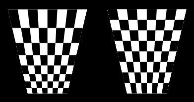
左边的两个三角形具有uv(strq),根据this,右边的两个三角形是该透视校正的修改版本。
数字和着色器:
tri1 = [Vec2(-0.5, -1), Vec2(0.5, -1), Vec2(1, 1)]
tri2 = [Vec2(-0.5, -1), Vec2(1, 1), Vec2(-1, 1)]

d1 = length of top edge = 2
d2 = length of bottom edge = 1

tri1_uv = [Vec4(0, 0, 0, d2 / d1), Vec4(d2 / d1, 0, 0, d2 / d1), Vec4(1, 1, 0, 1)]
tri2_uv = [Vec4(0, 0, 0, d2 / d1), Vec4(1, 1, 0, 1), Vec4(0, 1, 0, 1)]
void main()
{
    gl_FragColor = texture2D(colormap, vec2(gl_TexCoord[0].x / glTexCoord[0].w, gl_TexCoord[0].y);
}
所以..只有U是透视的,V是线性的。