我需要将一个矩形贴图变成极坐标格式的贴图。为了更清楚地说明,我将进行如下阐述:
我有这张图片: 然后我要使用着色器将其变形成如下所示的样子:
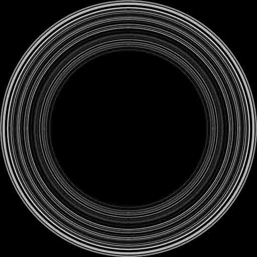
 然后我将把它映射到一个平面上。如何实现这个过程呢?非常感谢您提供的帮助!
我有这张图片:
然后我要使用着色器将其变形成如下所示的样子:
然后我将把它映射到一个平面上。如何实现这个过程呢?非常感谢您提供的帮助!
然后我要使用着色器将其变形成如下所示的样子:
然后我将把它映射到一个平面上。如何实现这个过程呢?非常感谢您提供的帮助! tc 进行)转换为极坐标即可。由于中心位于(0.5,0.5),因此我们首先必须进行偏移。
vec2 x=tc - vec2(0.5,0.5);
float radius=length(x);
float angle=atan(x.y, x.x);
现在您需要做的就是将范围映射回[0,1]纹理空间。这里的最大半径将为0.5,因此您只需使用2 * radius作为s坐标,而角度将在[-pi,pi]之间,因此您应该将其映射到t坐标的[0,1]区间。
更新1
到目前为止,我留下了一些细节。从您的图像中可以清楚地看出,您不希望将内圆映射到纹理上。但是这很容易被纳入考虑。我假设这里有两个半径:r_inner,它是内圆的半径,和r_outer,它是您想要将外部部分映射到的半径。让我简述一个简单的片段着色器:
#version ...
precision ...
varying vec2 tc; // texcoords from vertex shader
uniform sampler2D tex;
#define PI 3.14159265358979323844
void main ()
{
const float r_inner=0.25;
const float t_outer=0.5;
vec2 x = v_tex - vec2(0.5);
float radius = length(x);
float angle = atan(x.y, x.x);
vec2 tc_polar; // the new polar texcoords
// map radius so that for r=r_inner -> 0 and r=r_outer -> 1
tc_polar.s = ( radius - r_inner) / (r_outer - r_inner);
// map angle from [-PI,PI] to [0,1]
tc_polar.t = angle * 0.5 / PI + 0.5;
// texture mapping
gl_FragColor = texture2D(tex, tc_polar);
}
现在还有一个细节缺失。上面生成的映射会生成超出 [0,1] 范围的纹理坐标,对于任何具有黑色的位置,纹理采样都不会自动给出黑色。最简单的解决方案是仅使用 GL_CLAMP_TO_BORDER 模式来设置 GL_TEXTURE_WRAP_S(默认边框颜色为 (0,0,0,0),因此您可能不需要指定它或者您可以将 GL_TEXTURE_BORDER_COLOR 明确设置为 (0,0,0,1) 如果您使用 alpha 混合并且不希望通过这种方式获得任何透明度)。这样,你就可以免费得到黑色了。其他选项是使用 GL_CLAMP_TO_EDGE 并在纹理的左右两端添加一个黑色像素列。另一种方法是向着色器添加一个分支,并检查 tc_polar.s 是否低于 0 或高于 1,但我不建议在这种情况下这样做。uniform float Angle; // range 2pi / 100000.0 to 1.0 (rounded down), exponential
uniform float AngleMin; // range -3.2 to 3.2
uniform float AngleWidth; // range 0.0 to 6.4
uniform float Radius; // range -10000.0 to 1.0
uniform float RadiusMin; // range 0.0 to 2.0
uniform float RadiusWidth; // range 0.0 to 2.0
uniform vec2 Center; // range: -1.0 to 3.0
uniform sampler2D Texture;
void main()
{
// Normalised texture coords
vec2 texCoord = gl_TexCoord[0].xy;
// Shift origin to texture centre (with offset)
vec2 normCoord;
normCoord.x = 2.0 * texCoord.x – Center.x;
normCoord.y = 2.0 * texCoord.y – Center.y;
// Convert Cartesian to Polar coords
float r = length(normCoord);
float theta = atan(normCoord.y, normCoord.x);
// The actual effect
r = (r < RadiusMin) ? r : (r > RadiusMin + RadiusWidth) ? r : ceil(r / Radius) * Radius;
theta = (theta < AngleMin) ? theta : (theta > AngleMin + AngleWidth) ? theta : floor(theta / Angle) * Angle;
// Convert Polar back to Cartesian coords
normCoord.x = r * cos(theta);
normCoord.y = r * sin(theta);
// Shift origin back to bottom-left (taking offset into account)
texCoord.x = normCoord.x / 2.0 + (Center.x / 2.0);
texCoord.y = normCoord.y / 2.0 + (Center.y / 2.0);
// Output
gl_FragColor = texture2D(Texture, texCoord);
}
shadertoy.com上玩弄这个着色器,而不是直接在WebGL中实现它。看一下https://www.shadertoy.com/view/Dt23DW。 - NoleshLibGDX库中使用了这个着色器,但我相信你可以根据环境进行一些更改后在任何地方使用它。 - Nolesh
t增加分辨率。 - NoleshGL_TEXTURE_WRAP_T模式设置为GL_REPEAT,并将t纹理坐标(现在在[0,1]范围内)乘以180。 - derhass