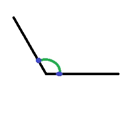
我在画布上有两个点,现在我能够像下面这张图片一样通过使用以下代码在这些点之间画一条直线:
canvas.drawLine(p1.x, p1.y, p2.x, p2.y, paint);
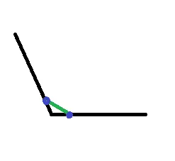
我想要像下面这张图片一样在两个点之间画弧线。
我该如何实现这样的效果。
我在画布上有两个点,现在我能够像下面这张图片一样通过使用以下代码在这些点之间画一条直线:
canvas.drawLine(p1.x, p1.y, p2.x, p2.y, paint);
我想要像下面这张图片一样在两个点之间画弧线。
我该如何实现这样的效果。
最终我从这段代码中找到了解决方案:
float radius = 20;
final RectF oval = new RectF();
oval.set(point1.x - radius, point1.y - radius, point1.x + radius, point1.y+ radius);
Path myPath = new Path();
myPath.arcTo(oval, startAngle, -(float) sweepAngle, true);
要计算startAngle,请使用以下代码:
int startAngle = (int) (180 / Math.PI * Math.atan2(point.y - point1.y, point.x - point1.x));
在这里,point1表示你想要开始绘制圆弧的位置。sweepAngle表示两条线之间的角度。我们需要像我问题中的蓝色点一样使用两个点来计算它。
可以像这样执行:
//Initialized paint on a class level object.
Paint p = new Paint();
p.setColor(Color.BLACK);
//Calculate the rect / bounds of oval
RectF rectF = new RectF(50, 20, 100, 80);

@Override
protected void onDraw(Canvas canvas) {
    //Do the drawing in onDraw() method of View.
    canvas.drawArc (rectF, 90, 45, false, p);
}
drawArc的第四个参数必须为false,否则它将绘制一个楔形。样式也需要是“STROKE”。 - Oliv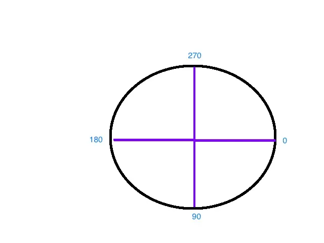 首先我们需要可视化坐标系的起始角度和扫描角度,然后问题就会变得更加清晰。
如果您只想要圆形的右上部分,可以尝试以下方法:
 val rect = RectF(0f, 0f, 500f, 300f)
        val paint = Paint()
        paint.apply {
            strokeWidth = 5f
            setStyle(Paint.Style.STROKE)
            color = COLOR.BLUE
        }
         path.addArc(rect, 270f, 90f)
..
这段文字的意思是:“根据上面的图示和‘扫描’90度向前,这个形状从270处开始。”
让我们再创建一个,这样你就能掌握了。这次让我们使用一个负值:我们想要从右侧开始创建一个半月形(弧形):
path.addArc(rect, 0f, -180f)
我们从0度开始“扫描”到了-180度。结果如下:
我想做一些有点不同的事情,它涉及计算扫描角和起始角。
我想展示一个弧形来表示从上到下的圆圈上的进度。
所以我的进度值从0到100,并且我想展示一个从顶部到底部开始填充圆圈的弧形,当进度为100时,弧形填满整个圆圈。
为了计算扫描角,我使用以下公式:
int sweepAngle = (int) (360 * (getProgress() / 100.f));
接下来是计算 startAngle
int startAngle = 270 - sweepAngle / 2;
起始角度是这样计算的:
因此,考虑到我已完成25%的进度。
sweepAngle = 90 degrees (90 degrees is quarter of a circle)
start angle = 225 (45 degrees away from 270)
用法:public void drawArc(RectF oval, float startAngle, float sweepAngle, boolean useCenter, Paint paint)
public void drawArc(float left, float top, float right, float bottom, float startAngle, float sweepAngle, boolean useCenter, Paint paint)
   RectF rectF = new RectF(left, top, right, bottom);

    // method 1
    canvas.drawArc (rectF, 90, 45, true,  paints[0]);

    // method 2
    if (Build.VERSION.SDK_INT >= Build.VERSION_CODES.LOLLIPOP) {
        canvas.drawArc (left, top, right, bottom, 0, 45, true, paints[1]);
    }
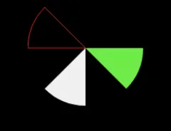
扫描角度指的是绘制顺时针扇形的角度,例如下面的代码:
private void drawArcs(Canvas canvas) {
    RectF rectF = new RectF(left, top, right, bottom);

    // white arc
    canvas.drawArc (rectF, 90, 45, true,  paints[0]);

    // Green arc
    if (Build.VERSION.SDK_INT >= Build.VERSION_CODES.LOLLIPOP) {
        canvas.drawArc (left, top, right, bottom, 0, 45, true, paints[1]);
    }

    // Red stroked arc
    if (Build.VERSION.SDK_INT >= Build.VERSION_CODES.LOLLIPOP) {
        canvas.drawArc (left, top, right, bottom, 180, 45, true,  paints[2]);
    }
}
结果将如下图所示:
 public class ArcDrawable extends Drawable {

    private int left, right, top, bottom;
    private  Paint[] paints = new Paint[3];
    private HashMap<Path, Paint> pathMap = new HashMap();


    public ArcDrawable() {

        // white paint
        Paint whitePaint = new Paint(Paint.ANTI_ALIAS_FLAG);
        whitePaint.setColor(Color.WHITE);
        paints[0]= whitePaint;

        // green paint
        Paint greenPaint = new Paint(Paint.ANTI_ALIAS_FLAG);
        greenPaint.setColor(Color.GREEN);
        paints[1]= greenPaint;

        // red paint
        Paint redPaint =new Paint(Paint.ANTI_ALIAS_FLAG);
        redPaint.setColor(Color.RED);
        redPaint.setStyle(Paint.Style.STROKE);
        paints[2]= redPaint;
    }

    @Override
    public void draw(Canvas canvas) {

        //----------USE PATHS----------
        // Define and use custom  Path
        for (Map.Entry<Path, Paint> entry : pathMap.entrySet()) {
            // Draw Path on respective Paint style
            canvas.drawPath(entry.getKey(),  entry.getValue());

        }

        // -------OR use conventional Style---------
        //drawArcs(canvas);

    }


    //Same result
    private void drawArcs(Canvas canvas) {
        RectF rectF = new RectF(left, top, right, bottom);

        // method 1
        canvas.drawArc (rectF, 90, 45, true,  paints[0]);

        // method 2
        if (Build.VERSION.SDK_INT >= Build.VERSION_CODES.LOLLIPOP) {
            canvas.drawArc (left, top, right, bottom, 0, 45, true, paints[1]);
        }

        // method two with stroke
        if (Build.VERSION.SDK_INT >= Build.VERSION_CODES.LOLLIPOP) {
            canvas.drawArc (left, top, right, bottom, 180, 45, true,  paints[2]);
        }
    }


    @Override
    protected void onBoundsChange(Rect bounds) {
        super.onBoundsChange(bounds);

        int width = bounds.width();
        int height = bounds.height();

        left = bounds.left;
        right = bounds.right;
        top = bounds.top;
        bottom = bounds.bottom;

        final int size = Math.min(width, height);
        final int centerX = bounds.left + (width / 2);
        final int centerY = bounds.top + (height / 2);

        pathMap.clear();
        //update pathmap using new bounds
        recreatePathMap(size, centerX, centerY);
        invalidateSelf();
    }


    private Path recreatePathMap(int size, int centerX, int centerY) {

        RectF rectF = new RectF(left, top, right, bottom);

        // first arc
        Path arcPath = new Path();
        arcPath.moveTo(centerX,centerY);
        arcPath.arcTo (rectF, 90, 45);
        arcPath.close();
        // add to draw Map
        pathMap.put(arcPath, paints[0]);

        //second arc
        arcPath = new Path();
        arcPath.moveTo(centerX,centerY);
        if (Build.VERSION.SDK_INT >= Build.VERSION_CODES.LOLLIPOP) {
          arcPath.arcTo (rectF, 0, 45);
        }
        arcPath.close();
        // add to draw Map
        pathMap.put(arcPath, paints[1]);

        // third arc
        arcPath = new Path();
        arcPath.moveTo(centerX,centerY);
        if (Build.VERSION.SDK_INT >= Build.VERSION_CODES.LOLLIPOP) {
            arcPath.arcTo (rectF, 180, 45);

        }
        arcPath.close();
        // add to draw Map
        pathMap.put(arcPath, paints[2]);

        return arcPath;

    }

    @Override
    public void setAlpha(int alpha) {

    }

    @Override
    public void setColorFilter(@Nullable ColorFilter colorFilter) {

    }

    @Override
    public int getOpacity() {
        return 0;
    }


}
Path path = new Path();
float startX = 0;
float startY = 2;
float controlX = 2;
float controlY = 4;
float endX = 4
float endY = 2
conePath.cubicTo(startX, startY, controlX, controlY,endX, endY);
Paint paint = new Paint();
paint.setARGB(200, 62, 90, 177);
paint.setStyle(Paint.Style.FILL);
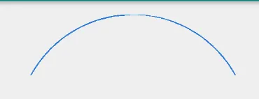
canvas.drawPath(path, paint)
绘制弧形的示例。
public static Bitmap clipRoundedCorner(Bitmap bitmap, float r, boolean tr, boolean tl, boolean bl, boolean br)
{
    int W = bitmap.getWidth();
    int H = bitmap.getHeight();

    if (r < 0)
        r = 0;

    int smallLeg = W;

    if(H < W )
        smallLeg = H;

    if (r > smallLeg)
        r = smallLeg / 2;

    float lineStop = r/2;

    Path path = new Path();
    path.moveTo(0,0);

    if(tr)
    {
        path.moveTo(0, lineStop);
        path.arcTo(new RectF(0,0, r,r), 180, 90, false);
    }

    path.lineTo(W-lineStop, 0);

    if(tl)
        path.arcTo(new RectF(W-r,0, W,r), 270, 90, false);
    else
        path.lineTo(W, 0);

    path.lineTo(W, H-lineStop);

    if(bl)
        path.arcTo(new RectF(W-r,H-r, W,H), 0, 90, false);
    else
        path.lineTo(W, H);

    path.lineTo(lineStop, H);

    if(br)
        path.arcTo(new RectF(0,H-r, r,H), 90, 90, false);
    else
        path.lineTo(0,H);

    if(tr)
        path.lineTo(0,lineStop);
    else
        path.lineTo(0,0);


    Bitmap output = Bitmap.createBitmap(W, H, Config.ARGB_8888);
    Canvas canvas = new Canvas(output);
    final Paint paint = new Paint(Paint.ANTI_ALIAS_FLAG);

    paint.setColor(Color.BLACK);
    canvas.drawPath(path, paint);

    paint.setXfermode(new PorterDuffXfermode(Mode.SRC_IN));
    canvas.drawBitmap(bitmap, 0, 0, paint);

    return output;
}