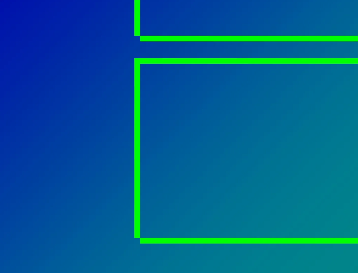
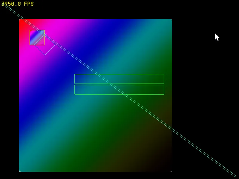
OpenGL:如何修复矩形(线或线环)中缺失的角像素

7

请看中间绿色矩形的左下角:

enter image description here

他们在左下角缺少一个像素。

enter image description here

我是这样画的:

class Rect: public StaticModel {
  public:
    Rect() {  
        constexpr glm::vec2 vertices[] {
                {-0.5,0.5},  // top left
                {0.5,0.5},  // top right
                {0.5,-0.5},  // bottom right
                {-0.5,-0.5},  // bottom left
        };
        _buf.bufferData<glm::vec2>(vertices,BufferUsage::StaticDraw);
        _idxBuf.bufferData<GLuint>({0,1,3,2,0,3,1,2},BufferUsage::StaticDraw);
    }

    void bind() const override {
        _buf.bindVertex(); 
        _idxBuf.bind();
    }

    void draw() const override {
        gl::drawElements(8,DrawMode::Lines);
    }

  private:
    VertexBuffer _buf{sizeof(glm::vec2)};
    ElementArrayBuffer _idxBuf{};
};

那段代码使用了我的一些辅助方法/类,但你应该能够理解它的作用。我尝试使用简单的GL_LINE_LOOP来绘制矩形,但是出现了同样的问题,所以现在我正在尝试使用GL_LINES,并按相同方向绘制所有线条:从上到下和从左到右,但仍然缺少一个像素。
这些坐标正在通过正交投影进行处理:
gl_Position = projection * model * vec4(inPos, 0.0, 1.0);

因此,着色器将那些0.5的坐标缩放到像素坐标,但我认为这不是一个舍入误差。

还有什么其他方法可以尝试使角落对齐吗?


1
@Rabbid76 这里我不是在寻找粗线,那是另一个问题(事实上,在第一张截图中我正在处理的就是那个长对角矩形),只是这个角落像素让我很烦恼。 - mpen
@Rabbid76 看起来实际上是一样的:https://i.imgur.com/h7Wt56M.png - mpen
你可能需要一些保守光栅化,但我不确定。 - Rabbid76
1个回答

1

OpenGL 给了很多自由,可以决定如何对线条进行光栅化。它要求某些理想的属性,但这些并不能防止在混合x-major(“水平”)和y-major(“垂直”)线条时出现间隙。

  • First thing, the "spirit of the spec" is to rasterize half-open lines; i.e. include the first vertex and exclude the final one. For that reason you should ensure that each vertex appears exactly once as a source and once as destination:

      _idxBuf.bufferData<GLuint>({0,1,1,2,2,3,3,0},BufferUsage::StaticDraw);
    

    This is contrary to your attempt of drawing "top to bottom and left to right".

    GL_LINE_LOOP already does that though, and you say that it doesn't solve the problem. That is indeed not guaranteed to solve the problem because you mix x-major and y-major lines here, but you still should follow the rule in order for the next point to work.

  • Next, I bet, some of your vertices fall right between the pixels; i.e. the window coordinates fractional part is exactly zero. When rasterizing such primitives the differences between different implementations (or in our case between x-major and y-major lines on the same implementation) become prominent.

    To solve that you can snap your vertices to the pixel grid:

      // xy - vertex in window coordinates, i.e. same as gl_FragCoord
      xy = floor(xy) + 0.5
    

    You can do this either in C++, or in the vertex shader. In either case you'll need to apply the projection and viewport transformations, and then undo them so that OpenGL can re-apply them afterwards. It's ugly, I know.

然而,实现像素完美的线条的唯一可靠方法是渲染三角形以覆盖形状(可以是每条线单独渲染或整个矩形),并在片段着色器中从gl_FragCoord.xy计算覆盖率。


等一下,你是说整数坐标在像素之间?0.5的位置是像素所在的位置吗?如果我把它看作一个网格,x=0就是窗口的左边缘,x=1就在第一个像素的右侧,那么这样讲也说得通。 - mpen
1
@mpen:是的,这就是OpenGL坐标系统的工作方式。(gl_FragCoord实际上可以在着色器中用pixel_center_integer覆盖,但默认情况下是您所描述的)。 - Yakov Galka
很好。我尝试将 layout (pixel_center_integer) in vec4 gl_FragCoord; 添加到我的 frag shader 中,但没有帮助。最终成功让另一个角落的像素消失了。然而,在我的 vertex shader 中添加 0.5 却奏效了!为什么我需要应用和撤销投影和视口变换?我在模型变换之后但投影变换之前添加它似乎可以工作。 - mpen
@mpen: pixel_center_integer 只会在片段着色器中改变 gl_FragCoord 的值。它不会影响固定管线光栅化。如果您使用的是将像素映射到坐标1:1的正交投影,则在模型和投影之后添加0.5可能适用于您。如果您有其他投影,则您的顶点着色器中的任何内容都不会以像素为单位测量,因此0.5将毫无意义。 - Yakov Galka

网页内容由stack overflow 提供, 点击上面的
可以查看英文原文,
原文链接