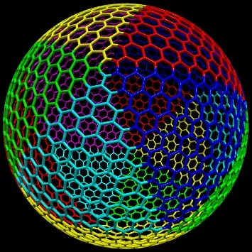
我正在尝试创建一个类似于这样的形状,由12个五边形组成的六边形,大小任意。
(图片来源)
唯一的问题是,我完全不知道需要什么样的代码来生成它!
目标是能够将3D空间中的一个点转换为网格上的位置坐标,或者反过来,获取网格位置并获得绘制网格所需的相关顶点。
我甚至不知道如何存储此网格的位置。每个三角形区域是否都有自己的2D坐标集?
我最可能会使用C#,但我更感兴趣的是要使用哪些算法以及它们如何工作的解释,而不仅仅是给我一段代码。
(图片来源)
唯一的问题是,我完全不知道需要什么样的代码来生成它!
目标是能够将3D空间中的一个点转换为网格上的位置坐标,或者反过来,获取网格位置并获得绘制网格所需的相关顶点。
我甚至不知道如何存储此网格的位置。每个三角形区域是否都有自己的2D坐标集?
我最可能会使用C#,但我更感兴趣的是要使用哪些算法以及它们如何工作的解释,而不仅仅是给我一段代码。
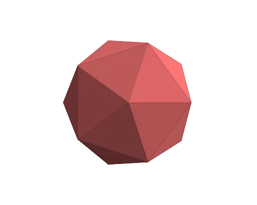
你要寻找的多面体可以由一个二十面体生成 -- 用一个二十面体初始化网格。
我们对网格应用了一个"Truncate"操作(Conway符号t)(此球形映射为足球)。
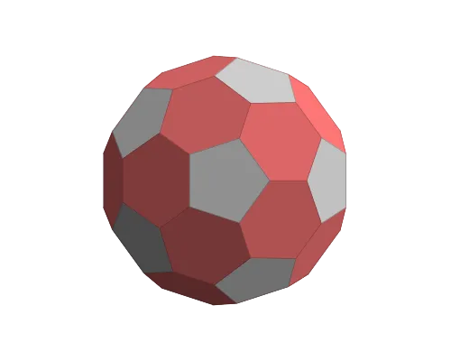
我们应用了"Dual"运算符(Conway符号d)。
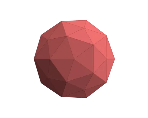
我们再次应用了"Truncate"操作。此时配方为tdtI(从右边阅读!)。你已经可以看到这个过程了。
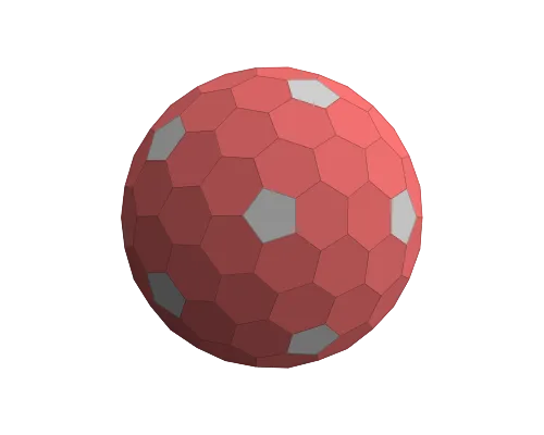
重复步骤3和4,直到满意为止。
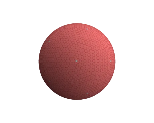
dtdtdtdtI 的网格示例。
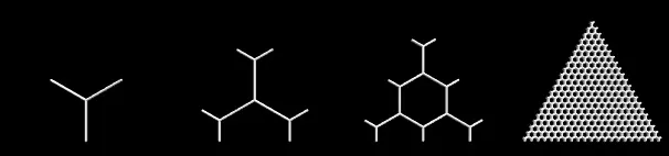
 这很容易实现。我建议使用数据结构,使得遍历相邻的顶点、边等变得容易,例如使用有向边或半边数据结构来处理您的网格。您只需要为您要查找的形状实现截取和对偶操作即可。
n的六边形网格重叠,使三角形的角与六边形中心重合,见n = 0,1,2,20的示例:
 2. 计算二十面体的顶点并定义其20个三角形面(见下面的代码)。二十面体的顶点定义了五边形的中心,二十面体的面定义了映射六边形网格的剪切块。(二十面体将球面表面细分为三角形的最好的正则划分,即划分为相等的等边三角形。其他这样的划分可以从四面体或八面体中导出;然后在三角形的角上会有三角形或正方形。此外,更少更大的三角形将使平面网格映射到曲面上的任何扭曲更加明显。因此,选择二十面体作为三角形剪切块的基础有助于最小化六边形的扭曲。)
n = 10的六边形网格的三角形剪切映射到一个球面三角形(由二十面体的一个面定义),以及将该网格映射到覆盖整个球体的所有这些球面三角形的插图(不同的映射使用不同的颜色):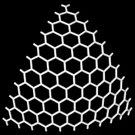
from math import sin,cos,acos,sqrt,pi
s,c = 2/sqrt(5),1/sqrt(5)
topPoints = [(0,0,1)] + [(s*cos(i*2*pi/5.), s*sin(i*2*pi/5.), c) for i in range(5)]
bottomPoints = [(-x,y,-z) for (x,y,z) in topPoints]
icoPoints = topPoints + bottomPoints
icoTriangs = [(0,i+1,(i+1)%5+1) for i in range(5)] +\
             [(6,i+7,(i+1)%5+7) for i in range(5)] +\
             [(i+1,(i+1)%5+1,(7-i)%5+7) for i in range(5)] +\
             [(i+1,(7-i)%5+7,(8-i)%5+7) for i in range(5)]
以下是将固定三角形(点)映射到球面三角形的Python代码,使用双倍球面线性插值:
# barycentric coords for triangle (-0.5,0),(0.5,0),(0,sqrt(3)/2)
def barycentricCoords(p):
  x,y = p
  # l3*sqrt(3)/2 = y
  l3 = y*2./sqrt(3.)
  # l1 + l2 + l3 = 1
  # 0.5*(l2 - l1) = x
  l2 = x + 0.5*(1 - l3)
  l1 = 1 - l2 - l3
  return l1,l2,l3

from math import atan2
def scalProd(p1,p2):
  return sum([p1[i]*p2[i] for i in range(len(p1))])
# uniform interpolation of arc defined by p0, p1 (around origin)
# t=0 -> p0, t=1 -> p1
def slerp(p0,p1,t):
  assert abs(scalProd(p0,p0) - scalProd(p1,p1)) < 1e-7
  ang0Cos = scalProd(p0,p1)/scalProd(p0,p0)
  ang0Sin = sqrt(1 - ang0Cos*ang0Cos)
  ang0 = atan2(ang0Sin,ang0Cos)
  l0 = sin((1-t)*ang0)
  l1 = sin(t    *ang0)
  return tuple([(l0*p0[i] + l1*p1[i])/ang0Sin for i in range(len(p0))])

# map 2D point p to spherical triangle s1,s2,s3 (3D vectors of equal length)
def mapGridpoint2Sphere(p,s1,s2,s3):
  l1,l2,l3 = barycentricCoords(p)
  if abs(l3-1) < 1e-10: return s3
  l2s = l2/(l1+l2)
  p12 = slerp(s1,s2,l2s)
  return slerp(p12,s3,l3)
[全面重新编辑 2017年10月18日]
几何图形的存储由您负责。您可以将其存储在某种网格中,也可以即时生成。我更喜欢将其存储在两个表格中。其中一个包含所有顶点(无重复项),另一个包含每个六边形使用的点的6个索引和一些额外信息(例如球面位置),以方便后续处理。
现在来看如何生成它:
创建六边形三角形
大小应为球体的半径。不包括角落的六边形,并且跳过三角形的最后一行(在径向和轴向上都是这样),因为这会导致在连接三角形段时重叠。
将60度的六边形三角形转换为72度的扇形
简单地转换为极坐标 (radius,angle),将三角形居中在0度周围。然后乘以 cos(angle)/cos(30) 的半径将其转换为扇形。然后将角度缩放比例调整为 72/60。这将使我们的三角形可连接…
复制并旋转三角形以填充五个五边形部分
只需旋转第一个三角形的点并存储为新的三角形即可。
计算z
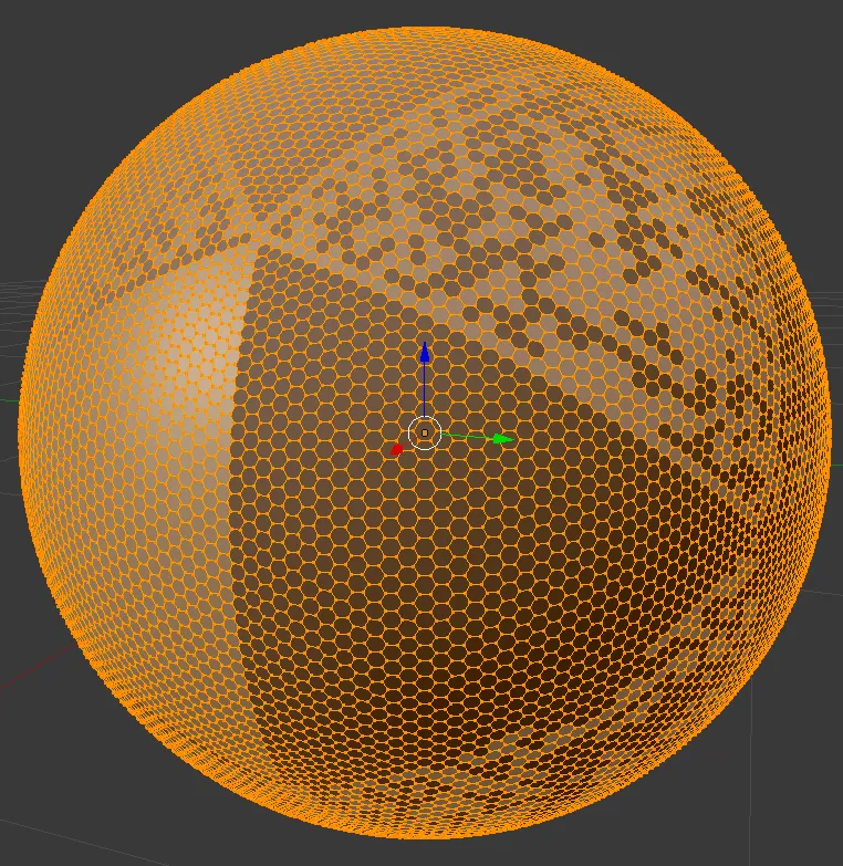
基于此 半球体的六角形贴片,您可以将2D地图中的距离转换为弧长,以尽可能地减小失真。
然而当我尝试它(下面的示例)时,六边形有点失真,因此深度和缩放需要进行一些微调。或者稍后进行后处理。
将半球形复制以形成一个球体
只需复制点/六边形并否定z轴(或旋转180度,如果要保留绕组顺序)即可。
添加赤道和所有丢失的五边形和六边形
您应该使用相邻六边形的坐标,以便不会给网格增加更多的失真和重叠。这里是预览:
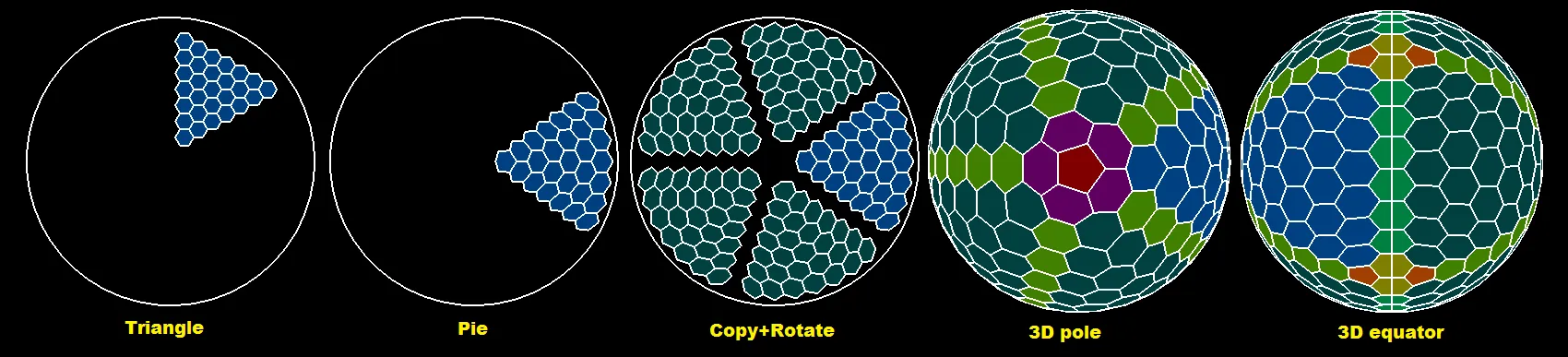
蓝色是起始三角形。深蓝色是其副本。红色是极点五边形。暗绿色是赤道,浅绿色是三角形之间的连接线。在黄色的是靠近深橙色五边形的失踪赤道六边形。
这里是一个简单的C++ OpenGL示例(来自于#4中的链接):
//$$---- Form CPP ----
//---------------------------------------------------------------------------
#include <vcl.h>
#include <math.h>
#pragma hdrstop
#include "win_main.h"
#include "gl/OpenGL3D_double.cpp"
#include "PolyLine.h"
//---------------------------------------------------------------------------
#pragma package(smart_init)
#pragma resource "*.dfm"
TMain *Main;
OpenGLscreen scr;
bool _redraw=true;
double animx=  0.0,danimx=0.0;
double animy=  0.0,danimy=0.0;
//---------------------------------------------------------------------------
PointTab     pnt;   // (x,y,z)

struct _hexagon
    {
    int ix[6];      // index of 6 points, last point duplicate for pentagon
    int a,b;        // spherical coordinate
    DWORD col;      // color

    // inline
    _hexagon()      {}
    _hexagon(_hexagon& a)   { *this=a; }
    ~_hexagon() {}
    _hexagon* operator = (const _hexagon *a) { *this=*a; return this; }
    //_hexagon* operator = (const _hexagon &a) { ...copy... return this; }
    };
List<_hexagon> hex;
//---------------------------------------------------------------------------
// https://dev59.com/K1YN5IYBdhLWcg3w27cv#46787885
//---------------------------------------------------------------------------
void hex_sphere(int N,double R)
    {
    const double c=cos(60.0*deg);
    const double s=sin(60.0*deg);
    const double sy=       R/(N+N-2);
    const double sz=sy/s;
    const double sx=sz*c;
    const double sz2=0.5*sz;

    const int na=5*(N-2);
    const int nb=  N;
    const int b0=  N;
    double *q,p[3],ang,len,l,l0,ll;
    int i,j,n,a,b,ix;
    _hexagon h,*ph;

    hex.allocate(na*nb);
    hex.num=0;
    pnt.reset3D(N*N);
    b=0; a=0; ix=0;

    // generate triangle hex grid
    h.col=0x00804000;
    for (b=1;b<N-1;b++)                             // skip first line b=0
     for (a=1;a<b;a++)                              // skip first and last line
        {
        p[0]=double(a       )*(sx+sz);
        p[1]=double(b-(a>>1))*(sy*2.0);
        p[2]=0.0;
        if (int(a&1)!=0) p[1]-=sy;
        ix=pnt.add(p[0]+sz2+sx,p[1]   ,p[2]); h.ix[0]=ix; //  2 1
        ix=pnt.add(p[0]+sz2   ,p[1]+sy,p[2]); h.ix[1]=ix; // 3   0
        ix=pnt.add(p[0]-sz2   ,p[1]+sy,p[2]); h.ix[2]=ix; //  4 5
        ix=pnt.add(p[0]-sz2-sx,p[1]   ,p[2]); h.ix[3]=ix;
        ix=pnt.add(p[0]-sz2   ,p[1]-sy,p[2]); h.ix[4]=ix;
        ix=pnt.add(p[0]+sz2   ,p[1]-sy,p[2]); h.ix[5]=ix;
        h.a=a;
        h.b=N-1-b;
        hex.add(h);
        } n=hex.num; // remember number of hexs for the first triangle

    // distort points to match area
    for (ix=0;ix<pnt.nn;ix+=3)
        {
        // point pointer
        q=pnt.pnt.dat+ix;
        // convert to polar coordinates
        ang=atan2(q[1],q[0]);
        len=vector_len(q);
        // match area of pentagon (72deg) triangle as we got hexagon (60deg) triangle
        ang-=60.0*deg;  // rotate so center of generated triangle is angle 0deg
        while (ang>+60.0*deg) ang-=pi2;
        while (ang<-60.0*deg) ang+=pi2;
        len*=cos(ang)/cos(30.0*deg);        // scale radius so triangle converts to pie
        ang*=72.0/60.0;                     // scale up angle so rotated triangles merge
        // convert back to cartesian
        q[0]=len*cos(ang);
        q[1]=len*sin(ang);
        }

    // copy and rotate the triangle to cover pentagon
    h.col=0x00404000;
    for (ang=72.0*deg,a=1;a<5;a++,ang+=72.0*deg)
     for (ph=hex.dat,i=0;i<n;i++,ph++)
        {
        for (j=0;j<6;j++)
            {
            vector_copy(p,pnt.pnt.dat+ph->ix[j]);
            rotate2d(-ang,p[0],p[1]);
            h.ix[j]=pnt.add(p[0],p[1],p[2]);
            }
        h.a=ph->a+(a*(N-2));
        h.b=ph->b;
        hex.add(h);
        }

    // compute z
    for (q=pnt.pnt.dat,ix=0;ix<pnt.nn;ix+=pnt.dn,q+=pnt.dn)
        {
        q[2]=0.0;
        ang=vector_len(q)*0.5*pi/R;
        q[2]=R*cos(ang);
        ll=fabs(R*sin(ang)/sqrt((q[0]*q[0])+(q[1]*q[1])));
        q[0]*=ll;
        q[1]*=ll;
        }

    // copy and mirror the other half-sphere
    n=hex.num;
    for (ph=hex.dat,i=0;i<n;i++,ph++)
        {
        for (j=0;j<6;j++)
            {
            vector_copy(p,pnt.pnt.dat+ph->ix[j]);
            p[2]=-p[2];
            h.ix[j]=pnt.add(p[0],p[1],p[2]);
            }
        h.a= ph->a;
        h.b=-ph->b;
        hex.add(h);
        }

    // create index search table
    int i0,i1,j0,j1,a0,a1,ii[5];
    int **ab=new int*[na];
    for (a=0;a<na;a++)
        {
        ab[a]=new int[nb+nb+1];
        for (b=-nb;b<=nb;b++) ab[a][b0+b]=-1;
        }
    n=hex.num;
    for (ph=hex.dat,i=0;i<n;i++,ph++) ab[ph->a][b0+ph->b]=i;

    // add join ring
    h.col=0x00408000;
    for (a=0;a<na;a++)
        {
        h.a=a;
        h.b=0;
        a0=a;
        a1=a+1; if (a1>=na) a1-=na;
        i0=ab[a0][b0+1];
        i1=ab[a1][b0+1];
        j0=ab[a0][b0-1];
        j1=ab[a1][b0-1];
        if ((i0>=0)&&(i1>=0))
         if ((j0>=0)&&(j1>=0))
            {
            h.ix[0]=hex[i1].ix[1];
            h.ix[1]=hex[i0].ix[0];
            h.ix[2]=hex[i0].ix[1];
            h.ix[3]=hex[j0].ix[1];
            h.ix[4]=hex[j0].ix[0];
            h.ix[5]=hex[j1].ix[1];
            hex.add(h);
            ab[h.a][b0+h.b]=hex.num-1;
            }
        }

    // add 2x5 join lines
    h.col=0x00008040;
    for (a=0;a<na;a+=N-2)
     for (b=1;b<N-3;b++)
        {
        // +b hemisphere
        h.a= a;
        h.b=+b;
        a0=a-b; if (a0<  0) a0+=na; i0=ab[a0][b0+b+0];
        a0--;   if (a0<  0) a0+=na; i1=ab[a0][b0+b+1];
        a1=a+1; if (a1>=na) a1-=na; j0=ab[a1][b0+b+0];
                                    j1=ab[a1][b0+b+1];
        if ((i0>=0)&&(i1>=0))
         if ((j0>=0)&&(j1>=0))
            {
            h.ix[0]=hex[i0].ix[5];
            h.ix[1]=hex[i0].ix[4];
            h.ix[2]=hex[i1].ix[5];
            h.ix[3]=hex[j1].ix[3];
            h.ix[4]=hex[j0].ix[4];
            h.ix[5]=hex[j0].ix[3];
            hex.add(h);
            }
        // -b hemisphere
        h.a= a;
        h.b=-b;
        a0=a-b; if (a0<  0) a0+=na; i0=ab[a0][b0-b+0];
        a0--;   if (a0<  0) a0+=na; i1=ab[a0][b0-b-1];
        a1=a+1; if (a1>=na) a1-=na; j0=ab[a1][b0-b+0];
                                    j1=ab[a1][b0-b-1];
        if ((i0>=0)&&(i1>=0))
         if ((j0>=0)&&(j1>=0))
            {
            h.ix[0]=hex[i0].ix[5];
            h.ix[1]=hex[i0].ix[4];
            h.ix[2]=hex[i1].ix[5];
            h.ix[3]=hex[j1].ix[3];
            h.ix[4]=hex[j0].ix[4];
            h.ix[5]=hex[j0].ix[3];
            hex.add(h);
            }
        }

    // add pentagons at poles
    _hexagon h0,h1;
    h0.col=0x00000080;
    h0.a=0; h0.b=N-1; h1=h0; h1.b=-h1.b;
    p[2]=sqrt((R*R)-(sz*sz));
    for (ang=0.0,a=0;a<5;a++,ang+=72.0*deg)
        {
        p[0]=2.0*sz*cos(ang);
        p[1]=2.0*sz*sin(ang);
        h0.ix[a]=pnt.add(p[0],p[1],+p[2]);
        h1.ix[a]=pnt.add(p[0],p[1],-p[2]);
        }
    h0.ix[5]=h0.ix[4]; hex.add(h0);
    h1.ix[5]=h1.ix[4]; hex.add(h1);

    // add 5 missing hexagons at poles
    h.col=0x00600060;
    for (ph=&h0,b=N-3,h.b=N-2,i=0;i<2;i++,b=-b,ph=&h1,h.b=-h.b)
        {
        a =  1; if (a>=na) a-=na; ii[0]=ab[a][b0+b];
        a+=N-2; if (a>=na) a-=na; ii[1]=ab[a][b0+b];
        a+=N-2; if (a>=na) a-=na; ii[2]=ab[a][b0+b];
        a+=N-2; if (a>=na) a-=na; ii[3]=ab[a][b0+b];
        a+=N-2; if (a>=na) a-=na; ii[4]=ab[a][b0+b];
        for (j=0;j<5;j++)
            {
            h.a=((4+j)%5)*(N-2)+1;
            h.ix[0]=ph->ix[ (5-j)%5 ];
            h.ix[1]=ph->ix[ (6-j)%5 ];
            h.ix[2]=hex[ii[(j+4)%5]].ix[4];
            h.ix[3]=hex[ii[(j+4)%5]].ix[5];
            h.ix[4]=hex[ii[ j     ]].ix[3];
            h.ix[5]=hex[ii[ j     ]].ix[4];
            hex.add(h);
            }
        }

    // add 2*5 pentagons and 2*5 missing hexagons at equator
    h0.a=0; h0.b=N-1; h1=h0; h1.b=-h1.b;
    for (ang=36.0*deg,a=0;a<na;a+=N-2,ang-=72.0*deg)
        {
        p[0]=R*cos(ang);
        p[1]=R*sin(ang);
        p[2]=sz;
        i0=pnt.add(p[0],p[1],+p[2]);
        i1=pnt.add(p[0],p[1],-p[2]);
        a0=a-1;if (a0<  0) a0+=na;
        a1=a+1;if (a1>=na) a1-=na;
        ii[0]=ab[a0][b0-1]; ii[2]=ab[a1][b0-1];
        ii[1]=ab[a0][b0+1]; ii[3]=ab[a1][b0+1];
        // hexagons
        h.col=0x00008080;
        h.a=a; h.b=0;
        h.ix[0]=hex[ii[0]].ix[0];
        h.ix[1]=hex[ii[0]].ix[1];
        h.ix[2]=hex[ii[1]].ix[1];
        h.ix[3]=hex[ii[1]].ix[0];
        h.ix[4]=i0;
        h.ix[5]=i1;
        hex.add(h);
        h.a=a; h.b=0;
        h.ix[0]=hex[ii[2]].ix[2];
        h.ix[1]=hex[ii[2]].ix[1];
        h.ix[2]=hex[ii[3]].ix[1];
        h.ix[3]=hex[ii[3]].ix[2];
        h.ix[4]=i0;
        h.ix[5]=i1;
        hex.add(h);
        // pentagons
        h.col=0x000040A0;
        h.a=a; h.b=0;
        h.ix[0]=hex[ii[0]].ix[0];
        h.ix[1]=hex[ii[0]].ix[5];
        h.ix[2]=hex[ii[2]].ix[3];
        h.ix[3]=hex[ii[2]].ix[2];
        h.ix[4]=i1;
        h.ix[5]=i1;
        hex.add(h);
        h.a=a; h.b=0;
        h.ix[0]=hex[ii[1]].ix[0];
        h.ix[1]=hex[ii[1]].ix[5];
        h.ix[2]=hex[ii[3]].ix[3];
        h.ix[3]=hex[ii[3]].ix[2];
        h.ix[4]=i0;
        h.ix[5]=i0;
        hex.add(h);
        }

    // release index search table
    for (a=0;a<na;a++) delete[] ab[a];
    delete[] ab;
    }
//---------------------------------------------------------------------------
void hex_draw(GLuint style)     // draw hex
    {
    int i,j;
    _hexagon *h;
    for (h=hex.dat,i=0;i<hex.num;i++,h++)
        {
        if (style==GL_POLYGON) glColor4ubv((BYTE*)&h->col);
        glBegin(style);
        for (j=0;j<6;j++) glVertex3dv(pnt.pnt.dat+h->ix[j]);
        glEnd();
        }
    if (0)
    if (style==GL_POLYGON)
        {
        scr.text_init_pixel(0.1,-0.2);
        glColor3f(1.0,1.0,1.0);
        for (h=hex.dat,i=0;i<hex.num;i++,h++)
         if (abs(h->b)<2)
            {
            double p[3];
            vector_ld(p,0.0,0.0,0.0);
            for (j=0;j<6;j++)
             vector_add(p,p,pnt.pnt.dat+h->ix[j]);
            vector_mul(p,p,1.0/6.0);
            scr.text(p[0],p[1],p[2],AnsiString().sprintf("%i,%i",h->a,h->b));
            }
        scr.text_exit_pixel();
        }
    }
//---------------------------------------------------------------------------
void TMain::draw()
    {
    scr.cls();
    int x,y;

    glMatrixMode(GL_MODELVIEW);
    glLoadIdentity();
    glTranslatef(0.0,0.0,-5.0);
    glRotated(animx,1.0,0.0,0.0);
    glRotated(animy,0.0,1.0,0.0);

    hex_draw(GL_POLYGON);

    glMatrixMode(GL_MODELVIEW);
    glLoadIdentity();
    glTranslatef(0.0,0.0,-5.0+0.01);
    glRotated(animx,1.0,0.0,0.0);
    glRotated(animy,0.0,1.0,0.0);

    glColor3f(1.0,1.0,1.0);
    glLineWidth(2);
    hex_draw(GL_LINE_LOOP);
    glCirclexy(0.0,0.0,0.0,1.5);
    glLineWidth(1);

    scr.exe();
    scr.rfs();
    }
//---------------------------------------------------------------------------
__fastcall TMain::TMain(TComponent* Owner) : TForm(Owner)
    {
    scr.init(this);
    hex_sphere(10,1.5);
    _redraw=true;
    }
//---------------------------------------------------------------------------
void __fastcall TMain::FormDestroy(TObject *Sender)
    {
    scr.exit();
    }
//---------------------------------------------------------------------------
void __fastcall TMain::FormPaint(TObject *Sender)
    {
    _redraw=true;
    }
//---------------------------------------------------------------------------
void __fastcall TMain::FormResize(TObject *Sender)
    {
    scr.resize();
    glMatrixMode(GL_PROJECTION);
    glLoadIdentity();
    gluPerspective(60,float(scr.xs)/float(scr.ys),0.1,100.0);
    _redraw=true;
    }
//-----------------------------------------------------------------------
void __fastcall TMain::Timer1Timer(TObject *Sender)
    {
    animx+=danimx; if (animx>=360.0) animx-=360.0; _redraw=true;
    animy+=danimy; if (animy>=360.0) animy-=360.0; _redraw=true;
    if (_redraw) { draw(); _redraw=false; }
    }
//---------------------------------------------------------------------------
void __fastcall TMain::FormKeyDown(TObject *Sender, WORD &Key, TShiftState Shift)
    {
    Caption=Key;
    if (Key==40){ animx+=2.0; _redraw=true; }
    if (Key==38){ animx-=2.0; _redraw=true; }
    if (Key==39){ animy+=2.0; _redraw=true; }
    if (Key==37){ animy-=2.0; _redraw=true; }
    }
//---------------------------------------------------------------------------
我知道这个索引有点混乱,而且由于我懒得制作统一的索引方式,螺旋规则也不能保证。注意每个六边形的a索引不是线性的,如果你想用它们来映射到2D地图上,您需要使用atan2在其中心点位置的x,y上重新计算它。
预览如下:
仍然存在一些扭曲。它们的原因是我们使用5个三角形在赤道连接(所以连接是保证的)。这意味着周长是5*R而不是6.28*R。然而,这可以通过场模拟进一步改进。只需取所有点并添加基于它们之间距离的拉力和约束在球面表面上。运行模拟,当振荡降至阈值以下时,您就得到了您的球格网...
另一个选择是找到一些方程来重新映射网格点(类似于我为三角形到扇区转换所做的方式),这将产生更好的结果。
5*R)与六边形的周长(6R)相比距离6.28*R更远,因此扭曲程度很高... - Spektre