我尝试了多种方法来实现插值并生成透视校正图像,但是没有一种建议的方法有效。
我的当前代码如下:
struct VertexStruct
{
  float4 normalizedPosition [[ position ]];
  float4 texCoord;
}

vertex VertexStruct testVertex(device float4 *vertices [[ buffer(0) ]],
                                     uint vid [[ vertex_id ]])
{
  VertexStruct outVertices;

  outVertices.normalizedPosition = ...;

  outVertices.texCoord = float4(vertices[vid].x, vertices[vid].y, 0.0, 127.0);

  return outVertices;
}

fragment half4 testFragment(VertexStruct inFrag [[ stage_in ]],
                            texture2d<half, access::sample> volume [[ texture(0) ]])
{
  float2 texCoord = float2(inFrag.texCoord.xy * (1.0 / inFrag.texCoord.w));
  constexpr sampler s(coord::normalized, filter::linear, address::clamp_to_zero);
  return volume.sample(s, texCoord);
}
纹理大小为128x128,顶点如下:
- 0,0
- 0,127
- 127,0
- 127,127
w应该有助于透视校正插值。这个技巧在OpenGL ES中已被报道可行,但在我的情况下,无论我是否开启都没有变化。得到的结果如下所示:
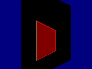
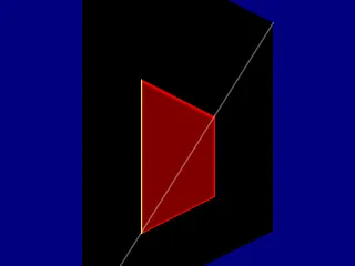
有人能看出错误吗?