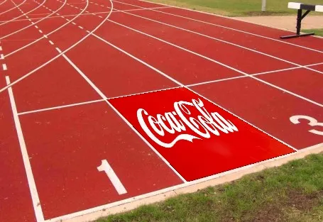
我已经使用Python和C++中的OpenCV进行了图像扭曲,可以看到可口可乐标志在我选择的角落处被扭曲:
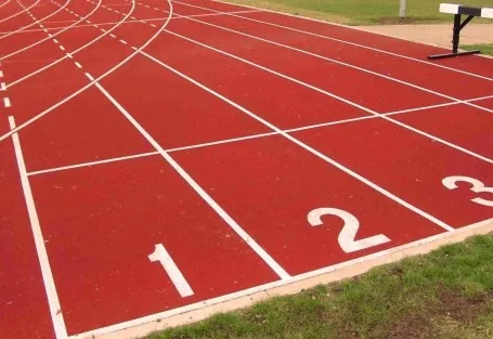
使用以下图像:
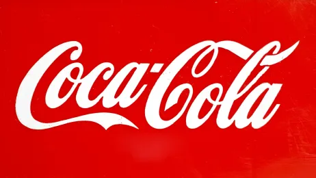
和这张图片:
我需要在OpenGL中做到这一点。 我会有:
Corners inside which I've to map the warped image
A homography matrix that maps the transformation of the logo image into the logo image you see inside the final image (using OpenCV's warpPerspective), something like this:
[[  2.59952324e+00,   3.33170976e-01,  -2.17014066e+02],
[  8.64133587e-01,   1.82580111e+00,  -3.20053715e+02],
[  2.78910149e-03,   4.47911310e-05,   1.00000000e+00]]
Main image (the running track image here)
Overlay image (the Coca Cola image here)
这可行吗?我已经阅读了很多相关的资料并开始学习OpenGL基础教程,但只凭我所学是否足够?OpenGL实现会更快,比如说大约10毫秒吗?
我正在尝试使用下面这个教程: http://ogldev.atspace.co.uk/www/tutorial12/tutorial12.html 我是不是在正确的方向上前进?我是OpenGL的新手,请谅解。谢谢。