如何在2D绘制透视校正网格

10

我有一个应用程序,在图像/照片上定义了一个真实世界的矩形,在二维平面上,由于你是从一个角度来看它,它可能不是一个严格意义上的矩形。

问题是,假设这个矩形需要有网格线,例如如果它是3x5,那么我需要从边1到边3画2条线,从边2到边4画4条线。

目前,我正在将每条线分成等距的部分,以获得所有网格线的起始和结束点。然而,矩形的角度越大,这些线就变得越不正确,因为远离你的水平线应该更加接近。

有人知道我应该搜索哪个算法的名称吗?

是的,我知道你可以在三维空间中完成这个任务,但是对于这个特定的应用程序,我只能使用二维平面。


因此,一个例子可能是在图片的窗口上尝试绘制一个矩形? - MSN
是的,那将是一个例子。 - Neil N
你在这个项目上有什么进展了吗?我需要类似的东西!谢谢。 - PyWebDesign
9个回答

15
这里是解决方案。
基本思路是通过对角线连接矩形的各个角来找到透视正确的矩形“中心点”。两条相交的线的交点就是透视正确的“中心点”。从那里,您将矩形细分为四个较小的矩形,并重复该过程。重复次数取决于您需要多么精确。您可以将其细分到几乎完美的透视下像素的大小以下。
然后,在子矩形中,只需应用标准的未校正的“纹理”三角形、矩形或其他形状即可。
您可以执行此算法而不必费力地构建一个“真正的”三维世界。如果您已经建模了一个真正的三维世界,但是您的纹理三角形在硬件上没有经过透视校正,或者您需要以高效的方式获取透视正确的平面而无需逐像素渲染技巧,则也很有用。

这个解决方案只适用于二的幂次方大小的网格吗? - Ipsquiggle
1
我猜应该是这样,但如果你是一个足够好的数学家,你可能能够推导出一个非线性变换矩阵,它反映了源像素和目标像素之间相同的关系。我不是这样的数学家,但我至少知道探究的诀窍,现在你也知道了。 - Breton

7

图片描述 
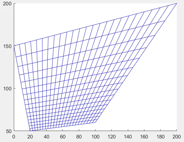
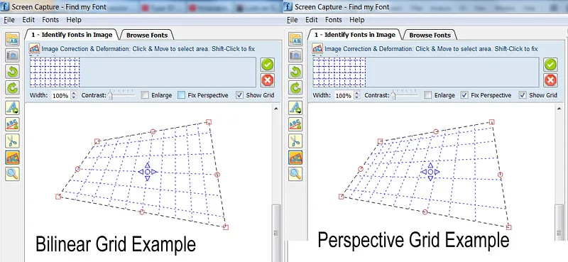
图片:双线性和透视变换示例(注意:两个图中顶部和底部水平网格线的高度实际上是其余线高度的一半)

========================================

我知道这是一个老问题,但我有一个通用解决方案,所以我决定发布它,希望对未来的读者有用。 下面的代码可以绘制任意透视网格,而不需要重复计算。

我实际上开始遇到类似的问题:绘制2D透视网格,然后转换下划线图像以恢复透视。

我开始在这里阅读: http://www.imagemagick.org/Usage/distorts/#bilinear_forward

然后在这里(Leptonica库): http://www.leptonica.com/affine.html

我在那里找到了这个:

当您从某个任意方向在有限距离上查看平面中的对象时,图像会发生额外的“楔形”畸变。这是一个投影变换,保持直线保持直线,但不保留线之间的角度。这种扭曲无法用线性仿射变换描述,实际上在分母中通过x和y依赖项的术语有所不同。

变换不是线性的,正如许多人在这个线程中指出的那样。它涉及解决8个方程的线性系统(一次)以计算所需的8个系数,然后您可以使用它们来转换任意数量的点。

为了避免将所有Leptonica库都包含在我的项目中,我从中提取了一些代码片段,删除了所有特殊的Leptonica数据类型和宏,修复了一些内存泄漏,并将其转换为C ++类(主要是为了封装原因),它只做一件事:将(Qt)QPointF浮点(x,y)坐标映射到相应的透视坐标。

如果您想将代码适应于另一个C ++库,则需要重新定义/替换的唯一内容是QPointF坐标类。

我希望一些未来的读者会发现它有用。 下面的代码分为3部分:

A.如何使用genImageProjective C ++类绘制2D透视网格的示例

B.genImageProjective.h文件

C.genImageProjective.cpp文件

//============================================================
// C++ Code Example on how to use the 
//     genImageProjective class to draw a perspective 2D Grid
//============================================================

#include "genImageProjective.h"

// Input: 4 Perspective-Tranformed points:
//        perspPoints[0] = top-left
//        perspPoints[1] = top-right
//        perspPoints[2] = bottom-right
//        perspPoints[3] = bottom-left
void drawGrid(QPointF *perspPoints)
{
(...)
        // Setup a non-transformed area rectangle
        // I use a simple square rectangle here because in this case we are not interested in the source-rectangle,
        //  (we want to just draw a grid on the perspPoints[] area)
        //   but you can use any arbitrary rectangle to perform a real mapping to the perspPoints[] area
        QPointF topLeft = QPointF(0,0);
        QPointF topRight = QPointF(1000,0);
        QPointF bottomRight = QPointF(1000,1000);
        QPointF bottomLeft = QPointF(0,1000);
        float width = topRight.x() - topLeft.x();
        float height = bottomLeft.y() - topLeft.y();

        // Setup Projective trasform object
        genImageProjective imageProjective;
        imageProjective.sourceArea[0] = topLeft;
        imageProjective.sourceArea[1] = topRight;
        imageProjective.sourceArea[2] = bottomRight;
        imageProjective.sourceArea[3] = bottomLeft;
        imageProjective.destArea[0] = perspPoints[0];
        imageProjective.destArea[1] = perspPoints[1];
        imageProjective.destArea[2] = perspPoints[2];
        imageProjective.destArea[3] = perspPoints[3];
        // Compute projective transform coefficients
        if (imageProjective.computeCoeefficients() != 0)
            return; // This can actually fail if any 3 points of Source or Dest are colinear

        // Initialize Grid parameters (without transform)
        float gridFirstLine = 0.1f; // The normalized position of first Grid Line (0.0 to 1.0)
        float gridStep = 0.1f;      // The normalized Grd size (=distance between grid lines: 0.0 to 1.0)

        // Draw Horizonal Grid lines
        QPointF lineStart, lineEnd, tempPnt;
        for (float pos = gridFirstLine; pos <= 1.0f; pos += gridStep)
        {
            // Compute Grid Line Start
            tempPnt = QPointF(topLeft.x(), topLeft.y() + pos*width);
            imageProjective.mapSourceToDestPoint(tempPnt, lineStart);
            // Compute Grid Line End
            tempPnt = QPointF(topRight.x(), topLeft.y() + pos*width);
            imageProjective.mapSourceToDestPoint(tempPnt, lineEnd);

            // Draw Horizontal Line (use your prefered method to draw the line)
            (...)
        }
        // Draw Vertical Grid lines
        for (float pos = gridFirstLine; pos <= 1.0f; pos += gridStep)
        {
            // Compute Grid Line Start
            tempPnt = QPointF(topLeft.x() + pos*height, topLeft.y());
            imageProjective.mapSourceToDestPoint(tempPnt, lineStart);
            // Compute Grid Line End
            tempPnt = QPointF(topLeft.x() + pos*height, bottomLeft.y());
            imageProjective.mapSourceToDestPoint(tempPnt, lineEnd);

            // Draw Vertical Line (use your prefered method to draw the line)
            (...)
        }
(...)
}

==========================================


//========================================
//C++ Header File: genImageProjective.h
//========================================

#ifndef GENIMAGE_H
#define GENIMAGE_H

#include <QPointF>

// Class to transform an Image Point using Perspective transformation
class genImageProjective
{
public:
    genImageProjective();

    int computeCoeefficients(void);
    int mapSourceToDestPoint(QPointF& sourcePoint, QPointF& destPoint);

public:
    QPointF sourceArea[4]; // Source Image area limits (Rectangular)
    QPointF destArea[4];   // Destination Image area limits (Perspectivelly Transformed)

private:
    static int gaussjordan(float  **a, float  *b, int n);

    bool coefficientsComputed;
    float vc[8];           // Vector of Transform Coefficients
};

#endif // GENIMAGE_H
//========================================


//========================================
//C++ CPP File: genImageProjective.cpp
//========================================

#include <math.h>
#include "genImageProjective.h"

// ----------------------------------------------------
// class genImageProjective
// ----------------------------------------------------
genImageProjective::genImageProjective()
{
    sourceArea[0] = sourceArea[1] = sourceArea[2] = sourceArea[3] = QPointF(0,0);
    destArea[0] = destArea[1] = destArea[2] = destArea[3] = QPointF(0,0);
    coefficientsComputed = false;
}


// --------------------------------------------------------------
// Compute projective transform coeeeficients
// RetValue: 0: Success, !=0: Error
/*-------------------------------------------------------------*
 *                Projective coordinate transformation         *
 *-------------------------------------------------------------*/
/*!
 *  computeCoeefficients()
 *
 *      Input:  this->sourceArea[4]: (source 4 points; unprimed)
 *              this->destArea[4]:   (transformed 4 points; primed)
 *              this->vc  (computed vector of transform coefficients)
 *      Return: 0 if OK; <0 on error
 *
 *  We have a set of 8 equations, describing the projective
 *  transformation that takes 4 points (sourceArea) into 4 other
 *  points (destArea).  These equations are:
 *
 *          x1' = (c[0]*x1 + c[1]*y1 + c[2]) / (c[6]*x1 + c[7]*y1 + 1)
 *          y1' = (c[3]*x1 + c[4]*y1 + c[5]) / (c[6]*x1 + c[7]*y1 + 1)
 *          x2' = (c[0]*x2 + c[1]*y2 + c[2]) / (c[6]*x2 + c[7]*y2 + 1)
 *          y2' = (c[3]*x2 + c[4]*y2 + c[5]) / (c[6]*x2 + c[7]*y2 + 1)
 *          x3' = (c[0]*x3 + c[1]*y3 + c[2]) / (c[6]*x3 + c[7]*y3 + 1)
 *          y3' = (c[3]*x3 + c[4]*y3 + c[5]) / (c[6]*x3 + c[7]*y3 + 1)
 *          x4' = (c[0]*x4 + c[1]*y4 + c[2]) / (c[6]*x4 + c[7]*y4 + 1)
 *          y4' = (c[3]*x4 + c[4]*y4 + c[5]) / (c[6]*x4 + c[7]*y4 + 1)
 *
 *  Multiplying both sides of each eqn by the denominator, we get
 *
 *           AC = B
 *
 *  where B and C are column vectors
 *
 *         B = [ x1' y1' x2' y2' x3' y3' x4' y4' ]
 *         C = [ c[0] c[1] c[2] c[3] c[4] c[5] c[6] c[7] ]
 *
 *  and A is the 8x8 matrix
 *
 *             x1   y1     1     0   0    0   -x1*x1'  -y1*x1'
 *              0    0     0    x1   y1   1   -x1*y1'  -y1*y1'
 *             x2   y2     1     0   0    0   -x2*x2'  -y2*x2'
 *              0    0     0    x2   y2   1   -x2*y2'  -y2*y2'
 *             x3   y3     1     0   0    0   -x3*x3'  -y3*x3'
 *              0    0     0    x3   y3   1   -x3*y3'  -y3*y3'
 *             x4   y4     1     0   0    0   -x4*x4'  -y4*x4'
 *              0    0     0    x4   y4   1   -x4*y4'  -y4*y4'
 *
 *  These eight equations are solved here for the coefficients C.
 *
 *  These eight coefficients can then be used to find the mapping
 *  (x,y) --> (x',y'):
 *
 *           x' = (c[0]x + c[1]y + c[2]) / (c[6]x + c[7]y + 1)
 *           y' = (c[3]x + c[4]y + c[5]) / (c[6]x + c[7]y + 1)
 *
 */
int genImageProjective::computeCoeefficients(void)
{
    int retValue = 0;
    int     i;
    float  *a[8];  /* 8x8 matrix A  */
    float  *b = this->vc; /* rhs vector of primed coords X'; coeffs returned in vc[] */

    b[0] = destArea[0].x();
    b[1] = destArea[0].y();
    b[2] = destArea[1].x();
    b[3] = destArea[1].y();
    b[4] = destArea[2].x();
    b[5] = destArea[2].y();
    b[6] = destArea[3].x();
    b[7] = destArea[3].y();

    for (i = 0; i < 8; i++)
        a[i] = NULL;
    for (i = 0; i < 8; i++)
    {
        if ((a[i] = (float *)calloc(8, sizeof(float))) == NULL)
        {
            retValue = -100; // ERROR_INT("a[i] not made", procName, 1);
            goto Terminate;
        }
    }

    a[0][0] = sourceArea[0].x();
    a[0][1] = sourceArea[0].y();
    a[0][2] = 1.;
    a[0][6] = -sourceArea[0].x() * b[0];
    a[0][7] = -sourceArea[0].y() * b[0];
    a[1][3] = sourceArea[0].x();
    a[1][4] = sourceArea[0].y();
    a[1][5] = 1;
    a[1][6] = -sourceArea[0].x() * b[1];
    a[1][7] = -sourceArea[0].y() * b[1];
    a[2][0] = sourceArea[1].x();
    a[2][1] = sourceArea[1].y();
    a[2][2] = 1.;
    a[2][6] = -sourceArea[1].x() * b[2];
    a[2][7] = -sourceArea[1].y() * b[2];
    a[3][3] = sourceArea[1].x();
    a[3][4] = sourceArea[1].y();
    a[3][5] = 1;
    a[3][6] = -sourceArea[1].x() * b[3];
    a[3][7] = -sourceArea[1].y() * b[3];
    a[4][0] = sourceArea[2].x();
    a[4][1] = sourceArea[2].y();
    a[4][2] = 1.;
    a[4][6] = -sourceArea[2].x() * b[4];
    a[4][7] = -sourceArea[2].y() * b[4];
    a[5][3] = sourceArea[2].x();
    a[5][4] = sourceArea[2].y();
    a[5][5] = 1;
    a[5][6] = -sourceArea[2].x() * b[5];
    a[5][7] = -sourceArea[2].y() * b[5];
    a[6][0] = sourceArea[3].x();
    a[6][1] = sourceArea[3].y();
    a[6][2] = 1.;
    a[6][6] = -sourceArea[3].x() * b[6];
    a[6][7] = -sourceArea[3].y() * b[6];
    a[7][3] = sourceArea[3].x();
    a[7][4] = sourceArea[3].y();
    a[7][5] = 1;
    a[7][6] = -sourceArea[3].x() * b[7];
    a[7][7] = -sourceArea[3].y() * b[7];

    retValue = gaussjordan(a, b, 8);

Terminate:
    // Clean up
    for (i = 0; i < 8; i++)
    {
        if (a[i])
            free(a[i]);
    }

    this->coefficientsComputed = (retValue == 0);
    return retValue;
}


/*-------------------------------------------------------------*
 *               Gauss-jordan linear equation solver           *
 *-------------------------------------------------------------*/
/*
 *  gaussjordan()
 *
 *      Input:   a  (n x n matrix)
 *               b  (rhs column vector)
 *               n  (dimension)
 *      Return:  0 if ok, 1 on error
 *
 *      Note side effects:
 *            (1) the matrix a is transformed to its inverse
 *            (2) the vector b is transformed to the solution X to the
 *                linear equation AX = B
 *
 *      Adapted from "Numerical Recipes in C, Second Edition", 1992
 *      pp. 36-41 (gauss-jordan elimination)
 */
#define  SWAP(a,b)   {temp = (a); (a) = (b); (b) = temp;}
int genImageProjective::gaussjordan(float  **a, float  *b, int n)
{
    int retValue = 0;
    int i, icol=0, irow=0, j, k, l, ll;
    int *indexc = NULL, *indexr = NULL, *ipiv = NULL;
    float  big, dum, pivinv, temp;

    if (!a)
    {
        retValue = -1; // ERROR_INT("a not defined", procName, 1);
        goto Terminate;
    }
    if (!b)
    {
        retValue = -2; // ERROR_INT("b not defined", procName, 1);
        goto Terminate;
    }

    if ((indexc = (int *)calloc(n, sizeof(int))) == NULL)
    {
        retValue = -3; // ERROR_INT("indexc not made", procName, 1);
        goto Terminate;
    }
    if ((indexr = (int *)calloc(n, sizeof(int))) == NULL)
    {
        retValue = -4; // ERROR_INT("indexr not made", procName, 1);
        goto Terminate;
    }
    if ((ipiv = (int *)calloc(n, sizeof(int))) == NULL)
    {
        retValue = -5; // ERROR_INT("ipiv not made", procName, 1);
        goto Terminate;
    }

    for (i = 0; i < n; i++)
    {
        big = 0.0;
        for (j = 0; j < n; j++)
        {
            if (ipiv[j] != 1)
            {
                for (k = 0; k < n; k++)
                {
                    if (ipiv[k] == 0)
                    {
                        if (fabs(a[j][k]) >= big)
                        {
                            big = fabs(a[j][k]);
                            irow = j;
                            icol = k;
                        }
                    }
                    else if (ipiv[k] > 1)
                    {
                        retValue = -6; // ERROR_INT("singular matrix", procName, 1);
                        goto Terminate;
                    }
                }
            }
        }
        ++(ipiv[icol]);

        if (irow != icol)
        {
            for (l = 0; l < n; l++)
                SWAP(a[irow][l], a[icol][l]);
            SWAP(b[irow], b[icol]);
        }

        indexr[i] = irow;
        indexc[i] = icol;
        if (a[icol][icol] == 0.0)
        {
            retValue = -7; // ERROR_INT("singular matrix", procName, 1);
            goto Terminate;
        }
        pivinv = 1.0 / a[icol][icol];
        a[icol][icol] = 1.0;
        for (l = 0; l < n; l++)
            a[icol][l] *= pivinv;
        b[icol] *= pivinv;

        for (ll = 0; ll < n; ll++)
        {
            if (ll != icol)
            {
                dum = a[ll][icol];
                a[ll][icol] = 0.0;
                for (l = 0; l < n; l++)
                    a[ll][l] -= a[icol][l] * dum;
                b[ll] -= b[icol] * dum;
            }
        }
    }

    for (l = n - 1; l >= 0; l--)
    {
        if (indexr[l] != indexc[l])
        {
            for (k = 0; k < n; k++)
                SWAP(a[k][indexr[l]], a[k][indexc[l]]);
        }
    }

Terminate:
    if (indexr)
        free(indexr);
    if (indexc)
        free(indexc);
    if (ipiv)
        free(ipiv);
    return retValue;
}


// --------------------------------------------------------------
// Map a source point to destination using projective transform
// --------------------------------------------------------------
// Params:
//  sourcePoint: initial point
//  destPoint:   transformed point
// RetValue: 0: Success, !=0: Error
// --------------------------------------------------------------
//  Notes:
//   1. You must call once computeCoeefficients() to compute
//      the this->vc[] vector of 8 coefficients, before you call
//      mapSourceToDestPoint().
//   2. If there was an error or the 8 coefficients were not computed,
//      a -1 is returned and destPoint is just set to sourcePoint value.
// --------------------------------------------------------------
int genImageProjective::mapSourceToDestPoint(QPointF& sourcePoint, QPointF& destPoint)
{
    if (coefficientsComputed)
    {
        float factor = 1.0f / (vc[6] * sourcePoint.x() + vc[7] * sourcePoint.y() + 1.);
        destPoint.setX( factor * (vc[0] * sourcePoint.x() + vc[1] * sourcePoint.y() + vc[2]) );
        destPoint.setY( factor * (vc[3] * sourcePoint.x() + vc[4] * sourcePoint.y() + vc[5]) );
        return 0;
    }
    else // There was an error while computing coefficients
    {
        destPoint = sourcePoint; // just copy the source to destination...
        return -1;               // ...and return an error
    }
}
//========================================

你似乎在描述投影变换或单应性变换。比如,OpenCV库(C++、Java、Python)有函数可用于估计这些变换并应用它们。 - Rui Marques
1
@Rui:谢谢你提供的信息。我其实一直在考虑未来要使用并尝试OpenCV,所以这是一个额外的动力去做它。 - Fivos Vilanakis
因此,当没有两条边共线时,此解决方案有效。当每条边与相对的边共线时,我可以找到一个仿射变换。但是如果一对边共线而另一对不共线呢?我该如何渲染它? - Ivan Kuckir
@IvanKuckir,我上面提出的解决方案在你描述的情况下运行良好。即使两个边对都共线(即在普通矩形情况下),它也可以工作,但在后一种情况下变成了线性变换;)(附注:我假设你所说的“共线”是指平行。如果你实际上是指共线,请提供一个图示,因为这超出了我的想象力)。 - Fivos Vilanakis
@FivosVilanakis非常抱歉,我在gaussjordan()的实现中出现了错误,当两条边平行时失败了...但我已经修复了它,现在它可以正常工作了 :) 顺便说一句,我正在使用它来转换照片,用户可以分别拖动图片的每个角落 :) http://i.imgur.com/tCDfhZx.png - Ivan Kuckir
@IvanKuckir 很高兴现在它可以工作了! :) 实际上我也是这样使用的:我让用户设置4个任意角落,然后将下面的图像区域转换为反向并修复透视畸变。 - Fivos Vilanakis

3
使用布雷顿细分方法(与蒙戈扩展方法相关)可以得到准确的任意二次幂细分。使用这些方法进行非二次幂细分,您将不得不将其细分为子像素间距,这可能会消耗大量计算资源。
然而,我认为您可以将Haga's Theorem的变体应用于透视正方形细分,从最接近2的幂开始产生任意细分,而无需继续细分。

Haga定理是一篇非常有趣的阅读,但它仅适用于正方形。对于我的长方形与可变的高/宽比率,我似乎找不到应用该定理的方法。 - Neil N
1
不是追求亚像素精度,我想我会为每个子区域做一个“二分查找”。因此,如果我需要将我的矩形分成三个部分,我基本上会进行二分查找,以达到33.33%和66.66%的一定精度,然后使用每个“部分”进行加权二等分(当我说“部分”时,如果我二等分4次,它将相当于透视正确的16分之一)。 - Neil N

2

最优雅和最快的解决方案是找到单应矩阵,它将矩形坐标映射到照片坐标。

有一个不错的矩阵库,只要你懂数学,这不应该是一项困难的任务。

关键词:共线性、单应性、直接线性变换

然而,上面的递归算法应该可以工作,但如果你的资源有限,射影几何可能是唯一的选择。


1

我认为所选答案并不是最好的解决方案。一种更好的解决方案是将矩形的透视(投影)变换应用于简单网格,如下所示的Matlab脚本和图像。您也可以使用C++和OpenCV实现此算法。

function drawpersgrid
sz      = [ 24, 16 ]; % [x y]
srcpt   = [ 0 0; sz(1) 0; 0 sz(2); sz(1) sz(2)];
destpt  = [ 20 50; 100 60; 0 150; 200 200;];

% make rectangular grid
[X,Y]   = meshgrid(0:sz(1),0:sz(2));

% find projective transform matching corner points
tform   = maketform('projective',srcpt,destpt);

% apply the projective transform to the grid
[X1,Y1] = tformfwd(tform,X,Y);

hold on;

%% find grid

for i=1:sz(2)
    for j=1:sz(1)
        x = [ X1(i,j);X1(i,j+1);X1(i+1,j+1);X1(i+1,j);X1(i,j)];
        y = [ Y1(i,j);Y1(i,j+1);Y1(i+1,j+1);Y1(i+1,j);Y1(i,j)];
        plot(x,y,'b');
    end
end
hold off;

Projective grid


我在Octave和Python中都尝试了一下,但基本上得到了相同的错误。 - naglas

0

给定绕y轴的旋转,特别是如果旋转表面是平面的,则透视图由垂直梯度生成。这些逐渐在透视中靠近。不要使用对角线来定义四个矩形,这可以在给定二次幂的情况下工作...定义两个矩形,左和右。如果继续将表面分成更窄的垂直段,则它们将比宽高。这可以容纳不是正方形的表面。如果旋转是绕x轴的,则需要水平梯度。


0
这是我想出来的一个几何解法。我不知道这个“算法”是否有一个名字。
假设你想先将“矩形”垂直划分为n份。
目标是在顶部线上放置点P1..Pn-1,我们可以通过它们画线到左右线相交的点,或者当这样的点不存在时平行于它们。
如果顶部和底部线是平行的,只需将这些点放置在角落之间等距分割的顶部线上。
否则,在左侧线上放置n个点Q1..Qn,使得这些点与左上角等距,并且i < j时Qi比Qj更靠近左上角。 为了将Q点映射到顶部线上,找到从Qn经过右上角的线与从顶部和底部线相交的平行线的交点S。现在连接S与Q1..Qn-1。新线与顶部线的交点即为所需的P点。
对于水平线也可以按照类似的方法进行操作。

0
在特殊情况下,当您垂直于边1和3时,可以将这些边分成相等的部分。然后画一条对角线,并通过对角线和之前绘制的分割线的每个交点绘制与边1平行的线。

-1

你需要做的是将其以3D(世界)形式呈现,然后将其投影到2D(屏幕)上。

这将需要您使用一个4D变换矩阵来将投影转化为4D齐次向量到3D齐次向量,然后您可以将其转换为2D屏幕空间向量。

我在Google上也找不到它,但一本好的计算机图形学书籍会有详细说明。

关键词包括投影矩阵,投影变换,仿射变换,齐次向量,世界空间,屏幕空间,透视变换,3D变换。

顺便说一句,这通常需要几节课才能解释清楚所有内容。所以祝你好运。


2
使用三维数学来实现这个功能是巨大的杀鸡焉用,而且计算复杂度也远远超出了需求。 - Sparr
1
这只是一堆数学计算,不需要任何输入输出。因此它会非常快速。 - Pyrolistical
3
“超快”是相对的。不使用3D数学会更加“超快”。将数百万个处理器周期应用于本应仅需要数千个处理器周期的问题,只会招来麻烦。如果他决定使用1024x1024网格而不是5x5网格,会发生什么? - Sparr

网页内容由stack overflow 提供, 点击上面的
可以查看英文原文,
原文链接