我尝试使用
请问我应该使用哪个变形函数来创建螺旋线呢?如何实现螺旋线的形状?
对应图片请查看链接: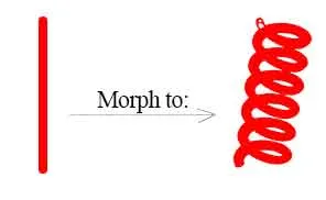
three.js和tween.js将一个矩形立方体变形成螺旋线。我已经搜索了一些相关问题,但没有找到适合我的答案。请问我应该使用哪个变形函数来创建螺旋线呢?如何实现螺旋线的形状?
对应图片请查看链接:
将你的管道存储为一组N个切片
每个(圆形)切片都需要中心点和法向量。
const int N=128;
struct slice { float p[3],n[3]; };
slice mesh[N];
在开始时将其初始化为管道(与y轴对齐)
for (int i=0;i<N;i++)
 {
 mesh[i].p[0]= 0.0;
 mesh[i].p[1]=-1.0+2.0*float(i)/float(N-1);
 mesh[i].p[2]= 0.0;
 mesh[i].n[0]= 0.0;
 mesh[i].n[1]=+1.0;
 mesh[i].n[2]= 0.0;
 }
编写可视化代码以表示此网格
您需要获取每个切片的周长点,并使用QUAD_STRIP或任何用于管道表面的基元将它们连接起来。最好使用TRIANGLE_FAN绕中心点绘制顶部和底部。
您可以使用我的glCircle3D in C++获得点,只需将其存储/使用即可...
在管道和螺旋之间进行插值
如果上述工作正常,您可以将中心位置和法线转换为半径可变的螺旋线,固定螺距m。所以我会尝试:
float a=6.283185307179586476925286766559*float(i*m)/float(N-1);
mesh[i].p[0] = r*cos(a);
mesh[i].p[2] = r*sin(a);
法线可以类似地计算,但我现在没有时间测试它,而且我的想象力也不是那么好,所以我会这样做:
mesh[i].n[0] = mesh[i].p[0] - mesh[i-1].p[0];
mesh[i].n[1] = mesh[i].p[1] - mesh[i-1].p[1];
mesh[i].n[2] = mesh[i].p[2] - mesh[i-1].p[2];
normalize(mesh[i].n); // set to unit vector
只需将切片1的法线复制到切片0即可。
动画
只需通过将r从零变为某个R来使网格动画。如果您想要连续效果,可以使用r=R*sin(t),其中t随着某个步骤的增加而增加...
[编辑1] C++ OpenGL 示例
如果您将上述所有内容放在一起,应该会得到类似于这样的东西:
//---------------------------------------------------------------------------
//         height  ,tube r  ,screw r ,screws
void helix(double h,double r,double R,double N)
    {
    int i,j,na;
    double pos[3]={ 0.0,0.0,0.0 },x[3],y[3],
           nor[3]={ 0.0,1.0,0.0 },ss,dy,a,da,b,db;
    na=double(N*36.0);              // 36 slices per screw
    const int nb=36+1;              // 36 points per circle slice
    dy=h/double(na);                // y axis step
    da=2.0*M_PI*N/double(na);       // screw angle step
    db=2.0*M_PI/double(nb-1);       // slice circle angle step
    ss=1.0/sqrt((R*R)+(dy*dy));     // normalization scale
    double pnt[nb*12],*p0=pnt,*p1=pnt+(nb*6),*pp;   // 2 slice point buffers (normal3d+vertex3d)*nb*2 = 12*nb
    for (a=0.0,i=0;i<na;i++,a+=da)
        {
        if (a>2.0*M_PI) a-=2.0*M_PI;
        // slice center
        pos[0]=R*cos(a);
        pos[1]+=dy;
        pos[2]=R*sin(a);
        // slice normal
        nor[0]=-ss*R*sin(a);
        nor[1]=+ss*dy;
        nor[2]=+ss*R*cos(a);
        // slice basis vectors x,y
        x[0]=cos(a);
        x[1]=0.0;
        x[2]=sin(a);
        // y = cross(x,nor)
        y[0]=             -(x[2]*nor[1]);
        y[1]=(x[2]*nor[0])-(x[0]*nor[2]);
        y[2]=(x[0]*nor[1]);
        // get the slice points (remember 2 slices for QUAD STRIP) to actual point buffer p1
        for (pp=p1,b=0.0,j=0;j<nb;j++,b+=db,pp+=6)
            {
            // normal
            pp[0]=(x[0]*cos(b))+(y[0]*sin(b));
            pp[1]=(x[1]*cos(b))+(y[1]*sin(b));
            pp[2]=(x[2]*cos(b))+(y[2]*sin(b));
            // position
            pp[3]=pos[0]+(pp[0]*r);
            pp[4]=pos[1]+(pp[1]*r);
            pp[5]=pos[2]+(pp[2]*r);
            }
        // if 2 slices done render the slice between last slice p0 and actual slice p1
        glBegin(GL_QUAD_STRIP);
        if (i) for (j=0;j<6*nb;j+=6)
            {
            glNormal3dv(p0+j+0);
            glVertex3dv(p0+j+3);
            glNormal3dv(p1+j+0);
            glVertex3dv(p1+j+3);
            }
        glEnd();
        // swap last,actual slice point buffers p0 <-> p1
        pp=p0; p0=p1; p1=pp;
        }
    }
//---------------------------------------------------------------------------
在OpenGL中呈现螺旋线。它从(0,0,0)开始,以(0,h,0)结束,其中:
r是管道的半径R是螺钉的半径h是螺旋线的高度/大小N是每个h的螺钉数量它生成顶点和法线信息,因此您可以使用照明。对于动画,我使用以下内容:
static double t=0.0; t+=0.1; if (t>=pi2) t-=pi2;
double R=sin(t); if (R<0.0) R=0.0;
glColor3f(1.0,1.0,1.0); helix(1.0,0.05,0.3*R,6.0);
正如您所看到的,正弦波的一半被忽略了,这样您就有时间实际看到管子而不带螺丝。这是带照明的输出:
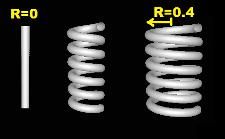
左边是未拧紧的管子(R=0)。右边是完全变形的螺旋,中间是介于两者之间的东西。
附言 如果你想让变形更有趣,还可以将N参数从0动画到某个常数。
Cube->Coil而不是Tube->Coil,这显然是我的疏忽。既然这个还没有被接受,那么问题来了,你真的需要一个立方体吗?(你的图片显示是圆筒形)如果确实需要,线圈应该有圆形剪切或方形剪切的电线? - Spektre