正常映射出了严重问题

4
我尝试在我的OpenGL应用程序中实现法线贴图,但是我无法使其正常工作。 
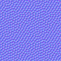
这个是漫反射贴图(我添加了棕色颜色),这个是法线贴图。
为了获得切线和副切线(在其他地方称为副法线)向量,我对我的网格中的每个三角形运行此函数:
void getTangent(const glm::vec3 &v0, const glm::vec3 &v1, const glm::vec3 &v2,
const glm::vec2 &uv0, const glm::vec2 &uv1, const glm::vec2 &uv2,
std::vector<glm::vec3> &vTangents, std::vector<glm::vec3> &vBiangents)
{
    // Edges of the triangle : postion delta
    glm::vec3 deltaPos1 = v1-v0;
    glm::vec3 deltaPos2 = v2-v0;

    // UV delta
    glm::vec2 deltaUV1 = uv1-uv0;
    glm::vec2 deltaUV2 = uv2-uv0;

    float r = 1.0f / (deltaUV1.x * deltaUV2.y - deltaUV1.y * deltaUV2.x);
    glm::vec3 tangent = (deltaPos1 * deltaUV2.y   - deltaPos2 * deltaUV1.y)*r;
    glm::vec3 bitangent = (deltaPos2 * deltaUV1.x   - deltaPos1 * deltaUV2.x)*r;

    for(int i = 0; i < 3; i++) {
        vTangents.push_back(tangent);
        vBiangents.push_back(bitangent);
    }
}

在此之后,我调用glBufferData将顶点、法线、UV坐标、切线和副切线上传到GPU。 顶点着色器:
#version 430

uniform mat4 ProjectionMatrix;
uniform mat4 CameraMatrix;
uniform mat4 ModelMatrix;

in vec3 vertex;
in vec3 normal;
in vec2 uv;
in vec3 tangent;
in vec3 bitangent;

out vec2 fsCoords;
out vec3 fsVertex;
out mat3 TBNMatrix;

void main()
{
    gl_Position = ProjectionMatrix * CameraMatrix * ModelMatrix * vec4(vertex, 1.0);

    fsCoords = uv;
    fsVertex = vertex;

    TBNMatrix = mat3(tangent, bitangent, normal);
}

片段着色器:

#version 430

uniform sampler2D diffuseMap;
uniform sampler2D normalMap;
uniform mat4 ModelMatrix;
uniform vec3 CameraPosition;

uniform struct Light {
    float ambient;
    vec3 position;
} light;
uniform float shininess;

in vec2 fsCoords;
in vec3 fsVertex;
in mat3 TBNMatrix;

out vec4 color;

void main()
{
    //base color
    const vec3 brownColor = vec3(153.0 / 255.0, 102.0 / 255.0, 51.0 / 255.0);
    color = vec4(brownColor * (texture(diffuseMap, fsCoords).rgb + 0.25), 1.0);//add a fixed base color (0.25), because its dark as hell

    //general vars
    vec3 normal = texture(normalMap, fsCoords).rgb * 2.0 - 1.0;
    vec3 surfacePos = vec3(ModelMatrix * vec4(fsVertex, 1.0));
    vec3 surfaceToLight = normalize(TBNMatrix * (light.position - surfacePos)); //unit vector
    vec3 eyePos = TBNMatrix * CameraPosition;

    //diffuse
    float diffuse = max(0.0, dot(normal, surfaceToLight));

    //specular
    float specular;
    vec3 incidentVector = -surfaceToLight; //unit
    vec3 reflectionVector = reflect(incidentVector, normal); //unit vector
    vec3 surfaceToCamera = normalize(eyePos - surfacePos); //unit vector
    float cosAngle = max(0.0, dot(surfaceToCamera, reflectionVector));
    if(diffuse > 0.0)
        specular = pow(cosAngle, shininess);

    //add lighting to the fragment color (no attenuation for now)
    color.rgb *= light.ambient;
    color.rgb += diffuse + specular;
}

我得到的图像完全不正确。(灯光位于相机上)
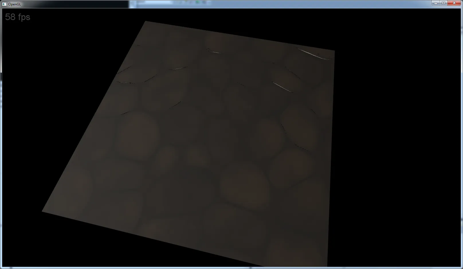
糟糕的结果

我在这里做错了什么?


我的赌注在片段着色器中的颜色设置/混合上... 1. 您正在多次设置输出颜色(如果我记得正确,某些图形驱动程序会出现大问题)2. 您正在添加“颜色”和“强度”,而不是“颜色*强度”,但我可能忽略了某些东西。3. 首先尝试正常/凸起着色(忽略环境、反射、高光...),然后逐个添加其余部分...始终检查着色器编译日志。 - Spektre
关于第三点,您的意思是我应该只使用漫反射光照吗?另外,我如何检查着色器编译日志?我的编译器不熟悉glsl,只熟悉c ++。 - McLovin
是的,您应该仅设置一次颜色变量,并从以下内容开始:
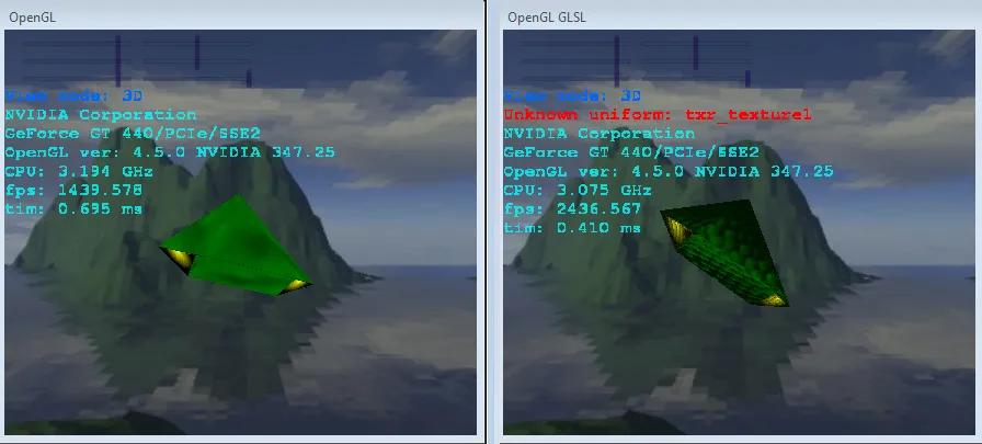
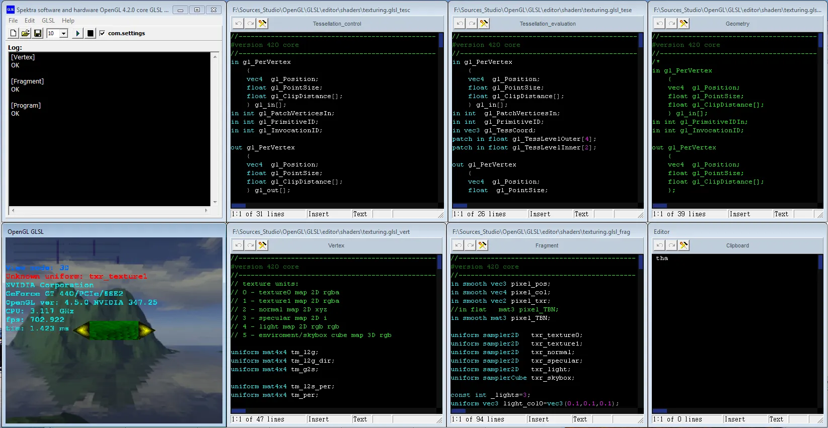
color.rgb=browncolor.rgb*fabs(dot(surface_normal,light_direction)); 我还添加了我的着色器答案,可以做到类似于您想要实现的内容。如果您不检查日志,则很容易错过某些内容,例如优化的I/O变量、语法错误等... - Spektre
2个回答

10

我认为问题出在片元着色器中的颜色设置或混合上......

  1. 您正在多次设置输出颜色

    如果我没记错,对于某些图形驱动程序,这会造成很大的问题,例如在以下行之后的所有内容:

    color = vec4(brownColor * (texture(diffuseMap, fsCoords).rgb + 0.25), 1.0);//add a fixed base color (0.25), because its dark as hell
    

    可能会被驱动程序删除...

  2. 您正在将颜色强度相加,而不是color*intensity

    但我可能会忽略某些东西。

  3. 首先尝试正常/凸起着色

    忽略环境、反射、高光...如果可以的话,逐个添加其他内容。始终检查着色器的编译日志

懒得进一步分析您的代码,所以这就是我做的方式:

凸起映射示例

左侧是太空飞船对象(类似于ZXS Elite的Viper),使用固定功能进行渲染。右侧是相同的对象(稍微旋转了一下),并使用GLSL着色器以及这个法线/凸起贴图

输入图像说明

[顶点]

//------------------------------------------------------------------
#version 420 core
//------------------------------------------------------------------
// texture units:
// 0 - texture0 map 2D rgba
// 1 - texture1 map 2D rgba
// 2 - normal map 2D xyz
// 3 - specular map 2D i
// 4 - light map 2D rgb rgb
// 5 - enviroment/skybox cube map 3D rgb

uniform mat4x4 tm_l2g;
uniform mat4x4 tm_l2g_dir;
uniform mat4x4 tm_g2s;

uniform mat4x4 tm_l2s_per;
uniform mat4x4 tm_per;

layout(location=0) in vec3 pos;
layout(location=1) in vec4 col;
layout(location=2) in vec2 txr;
layout(location=3) in vec3 tan;
layout(location=4) in vec3 bin;
layout(location=5) in vec3 nor;

out smooth vec3 pixel_pos;
out smooth vec4 pixel_col;
out smooth vec2 pixel_txr;
//out flat   mat3 pixel_TBN;
out smooth mat3 pixel_TBN;
//------------------------------------------------------------------
void main(void)
    {
    vec4 p;
    p.xyz=pos;
    p.w=1.0;
    p=tm_l2g*p;
    pixel_pos=p.xyz;
    p=tm_g2s*p;
    gl_Position=p;
    pixel_col=col;
    pixel_txr=txr;
    p.xyz=tan.xyz; p.w=1.0; pixel_TBN[0]=normalize((tm_l2g_dir*p).xyz);
    p.xyz=bin.xyz; p.w=1.0; pixel_TBN[1]=normalize((tm_l2g_dir*p).xyz);
    p.xyz=nor.xyz; p.w=1.0; pixel_TBN[2]=normalize((tm_l2g_dir*p).xyz);
    }
//------------------------------------------------------------------

[片段]

//------------------------------------------------------------------
#version 420 core
//------------------------------------------------------------------
in smooth vec3 pixel_pos;
in smooth vec4 pixel_col;
in smooth vec2 pixel_txr;
//in flat   mat3 pixel_TBN;
in smooth mat3 pixel_TBN;

uniform sampler2D   txr_texture0;
uniform sampler2D   txr_texture1;
uniform sampler2D   txr_normal;
uniform sampler2D   txr_specular;
uniform sampler2D   txr_light;
uniform samplerCube txr_skybox;

const int _lights=3;
uniform vec3 light_col0=vec3(0.1,0.1,0.1);
uniform vec3 light_dir[_lights]=         // direction to local star in ellipsoid space
    {
    vec3(0.0,0.0,+1.0),
    vec3(0.0,0.0,+1.0),
    vec3(0.0,0.0,+1.0),
    };
uniform vec3 light_col[_lights]=         // local star color * visual intensity
    {
    vec3(1.0,0.0,0.0),
    vec3(0.0,1.0,0.0),
    vec3(0.0,0.0,1.0),
    };

out layout(location=0) vec4 frag_col;

const vec4 v05=vec4(0.5,0.5,0.5,0.5);
const bool _blend=false;
const bool _reflect=true;
//------------------------------------------------------------------
void main(void)
    {
    float a=0.0,b,li;
    vec4 col,blend0,blend1,specul,skybox;
    vec3 normal;
    col=(texture2D(txr_normal,pixel_txr.st)-v05)*2.0;       // normal/bump maping
//  normal=pixel_TBN*col.xyz;
    normal=pixel_TBN[0];
    blend0=texture(txr_texture0,pixel_txr.st);
    blend1=texture(txr_texture1,pixel_txr.st);
    specul=texture(txr_specular,pixel_txr.st);
    skybox=texture(txr_skybox,normal);

    if (_blend)
        {
        a=blend1.a;
        blend0*=1.0-a;
        blend1*=a;
        blend0+=blend1;
        blend0.a=a;
        }

    col.xyz=light_col0; col.a=0.0; li=0.0;                          // normal shading (aj s bump mapingom)
    for (int i=0;i<_lights;i++)
            {
            b=dot(light_dir[i],normal.xyz);
            if (b<0.0) b=0.0;
//          b*=specul.r;
            li+=b;
            col.xyz+=light_col[i]*b;
            }
    col*=blend0;
    if (li<=0.1)
        {
        blend0=texture2D(txr_light,pixel_txr.st);
        blend0*=1.0-a;
        blend0.a=a;
        col+=blend0;
        }
    if (_reflect) col+=skybox*specul.r;
        col*=pixel_col;
    if (col.r<0.0) col.r=0.0;
    if (col.g<0.0) col.g=0.0;
    if (col.b<0.0) col.b=0.0;
    a=0.0;
    if (a<col.r) a=col.r;
    if (a<col.g) a=col.g;
    if (a<col.b) a=col.b;
    if (a>1.0)
        {
        a=1.0/a;
        col.r*=a;
        col.g*=a;
        col.b*=a;
        }
    frag_col=col;
    }
//------------------------------------------------------------------

这些源代码有点老,混合了不同的应用程序所需的内容。

所以只从中提取你需要的部分。如果你对变量名感到困惑,请留言给我......

  • tm_代表变换矩阵
  • l2g代表从局部坐标系到全局坐标系的变换
  • dir表示变换仅更改方向(偏移为0,0,0)
  • g2s代表从全局坐标到屏幕坐标...
  • per是透视变换...

GLSL编译日志

在着色器编译后,您必须通过程序获取其内容(而不是应用程序!)。我使用glGetShaderInfoLog函数来调用每个着色器、程序...

[注]

一些驱动程序会优化“未使用”的变量。正如你在图像中看到的,即使片段着色器在代码中具有txr_texture1,但是在此应用程序中没有使用融合,驱动程序也会自动删除它...

着色器日志可以显示很多信息(语法错误、警告...)

有一些针对着色器制作的GLSL IDE,但我更喜欢自己的,因为我可以直接在目标应用程序代码中使用它。我的看起来像这样:

GLSL IDE

每个文本窗口都是一个着色器源(顶点,片段...),右下角是剪贴板,左上角是最后一次编译后着色器日志,左下角是预览。我设法将其编码为Borland样式IDE(也包括键和语法高亮),我看到的其他IDE看起来类似(颜色不同)。无论如何,如果你想玩玩着色器,请下载此类应用程序或自己动手制作,它会帮助很多......

TBN创建也可能存在问题

您应该通过在每个顶点位置绘制彩色线条来直观地检查TBN向量(切线、副法线、法线)是否对应于物体表面。只是为了确保... 像这样:

normals


@Pilpel,精细地完成了编辑检查答案,如果您需要进一步的帮助,请评论我... - Spektre
谢谢您的回复,我没有太多时间分析您的代码(它也不是很易读),但我会尽快处理。只是想让您知道.. - McLovin
如何获取“tm_l2g_dir”矩阵? - Nolesh
@Nolesh 与 tm_l2g(类似于旧版 GL 中的 ModelView)相同,但原点设为 (0,0,0),您也可以使用原始的 tm_l2g,但在这种情况下,您需要为任何转换后的向量设置 w=0.0,因此 p.xyz=tan.xyz; p.w=0.0; pixel_TBN[0]=normalize((tm_l2g*p).xyz); ... - Spektre

1
我会尝试让你的代码工作。你有没有尝试过移动相机?
我没有看到你在使用变换矩阵、视图矩阵和模型矩阵来转换 TBN 矩阵。你有没有尝试使用原始法线(片段着色器中的 vec3 normal = TBNMatrix[2];)?
以下内容可能有所帮助。在顶点着色器中,你有:
uniform mat4 ProjectionMatrix;
uniform mat4 CameraMatrix;
uniform mat4 ModelMatrix;

然而在这里,只应使用这三个矩阵:
uniform mat4 PCM;
uniform mat4 MIT;         //could be mat3
uniform mat4 ModelMatrix; //could be mat3

在CPU上计算这些矩阵的乘积更加高效(并且与GPU计算结果相同,因为矩阵乘法是可交换的)。然后,可以使用这个乘积(PCM)每个顶点只需一次乘法来计算新位置:

gl_Position = PCM * vec4(vertex, 1.0);

MITModelMatrix 的逆转置矩阵,需要在 CPU 上计算。这可用于变换法线:

vec4 tang = ModelMatrix*vec4(tangent,0);
vec4 bita= ModelMatrix*vec4(bitangent,0);
vec4 norm= PCMIT*vec4(tangent,0);   
TBNMatrix = mat3(normalize(tang.xyz), normalize(bita.xyz), normalize(normal.xyz));

我不确定切线和副切线会发生什么,但这样法线将保持垂直于它们。这很容易证明。在此,我使用a ° b作为a和b向量的标量积。所以让n成为某个法线,a是表面上的某个向量(例如{bi}tangent,三角形的边缘),并且让A是任何转换。那么:
0 = a n = A^(-1) A a ° n = A a ° A^(-T) n = 0
我使用了等式A x ° y = x ° A^T y。因此,如果a垂直于n,则A a垂直于A^(-T) n,因此我们必须用矩阵的逆转置来转换它。然而,法线应该有长度为1,因此在变换后,它应该被归一化。
你也可以通过这样做获得垂直法线:
vec3 normal = normalize(cross(tangent, bitangent));

其中cross(a,b)是计算a和b的叉积的函数,它总是垂直于a和b。

对不起我的英语 :)


网页内容由stack overflow 提供, 点击上面的
可以查看英文原文,
原文链接