我尝试使用OpenGL和GLSL API在我的3D引擎中实现视差贴图,但显示不正确。为了学习和应用这种技术的复杂性,我受到了以下PDF教程(第16页、17页和18页)的启发:
首先,这是'CrazyBump'的显示(CrazyBump使用光照效果,但这里并不重要):
我试图修改比例和偏移值,但没有成功:显示仍然不正确。
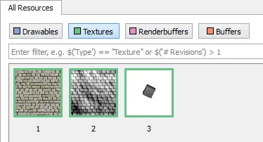
我认为我的位移纹理加载不正确,但事实并非如此(供参考,我使用NVIDIA NSight degugger)。
像素缓冲区从以下内容开始:
因此,我的问题似乎不是来自内存中加载的纹理。也许矩阵存在问题或者存在空间问题。我真的很迷失。
请问有人可以帮帮我吗?
非常感谢您提前的帮助!
https://www.opengl.org/sdk/docs/tutorials/TyphoonLabs/Chapter_4.pdf
为了产生一个非常基本的视差效果(没有任何照明效果),我需要使用2个纹理:- 1 diffuse (color) texture (BPP: 24 -> RGB - format: JPEG)
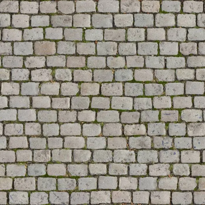
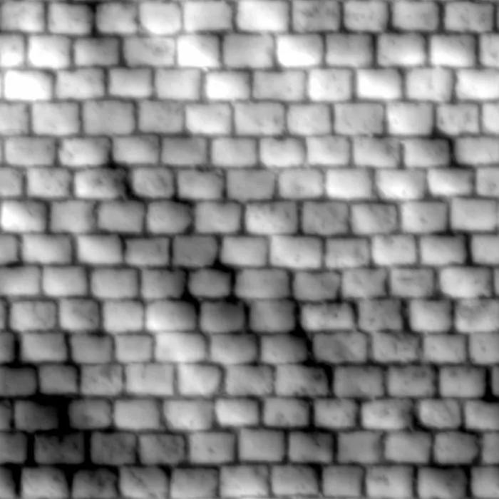
- 1 displacement (height/grayscale) texture (BPP: 24 -> RGB - format: JPEG)
首先,这是'CrazyBump'的显示(CrazyBump使用光照效果,但这里并不重要):
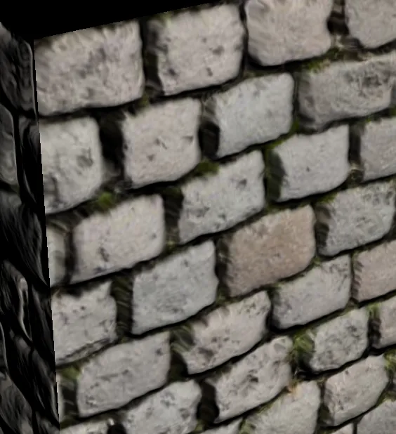
如您所见,视差效果被正确渲染。
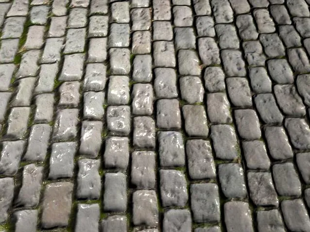
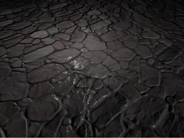
现在这里是我的场景中的渲染结果(使用由“CrazyBump”生成的相同位移纹理,没有亮度。我只想看到像上面那样的表面伪形变)。
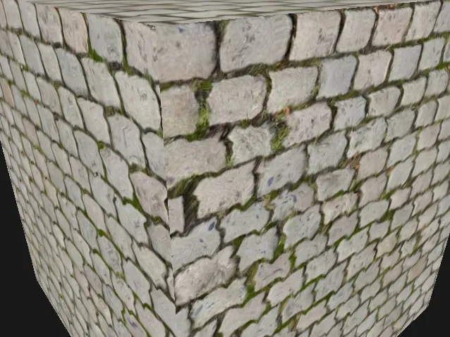
正如你所看到的,显示效果不同当然也不正确。
为了尝试产生相同的效果,我应用了我在帖子开头提到的PDF文件中的课程。
值得注意的是,我之前已经为我的引擎实现了“法线贴图”技术(因此切线和副切线向量是正确的!)。
为了执行我的着色器程序,我需要摄像机在世界空间中的位置和矩阵(ModelViewProj、ModelMatrix和NormalMatrix)。
这是我使用的客户端C++代码:
glm::mat4 modelViewMatrix = pRenderBatch->GetModelViewMatrix();

glm::mat3 normalMatrix = glm::mat3(glm::vec3(modelViewMatrix[0]),
    glm::vec3(modelViewMatrix[1]), glm::vec3(modelViewMatrix[2]));

this->SetUniform("ModelViewProjMatrix", pRenderBatch->GetModelViewProjMatrix());
this->SetUniform("ModelViewMatrix", modelViewMatrix);
this->SetUniform("NormalMatrix", normalMatrix);

//Bound on channel 0
glActiveTexture(GL_TEXTURE0);
this->m_pTextureManager.PushAndBindTexture(
    pMaterial->GetDiffuseTexture());
{
    this->SetUniform("DiffuseSampler", 0);
}
//Bound on channel 1
glActiveTexture(GL_TEXTURE1);
    this->m_pTextureManager.PushAndBindTexture(
        pMaterial->GetDisplacementTexture());
{
    this->SetUniform("HeightSampler", 1);
}
顶点着色器:
#version 440

/*
** Vertex attributes.
*/
layout (location = 0) in vec4 VertexPosition;
layout (location = 1) in vec2 VertexTexture;
layout (location = 2) in vec3 VertexNormal;
layout (location = 3) in vec3 VertexTangent;
layout (location = 4) in vec3 VertexBitangent;

/*
** Uniform matrices.
*/
uniform mat4 ModelViewProjMatrix;
uniform mat4 ModelViewMatrix;
uniform mat3 NormalMatrix;

//Outputs
out vec2 TexCoords;
out vec3 viewDir_TS;

/*
** Vertex shader entry point.
*/
void main(void)
{
    //Texture coordinates
    TexCoords = VertexTexture;

    //Vertex position in world space
    vec3 Position_CS = vec3(ModelViewMatrix * VertexPosition);
    //Vertex normal in world space
    vec3 Normal_CS = NormalMatrix * VertexNormal;
    //Vertex tangent in world space
    vec3 Tangent_CS = NormalMatrix * VertexTangent;
    //Vertex bitangent in world space
    vec3 Bitangent_CS = NormalMatrix * VertexBitangent;

    //View vector in world space
    vec3 viewDir_CS = -Position_CS;

    //TBN matrix
    mat3 TBN =  mat3(
        Tangent_CS.x, Bitangent_CS.x, Normal_CS.x,
        Tangent_CS.y, Bitangent_CS.y, Normal_CS.y,
        Tangent_CS.z, Bitangent_CS.z, Normal_CS.z);

    //2 others ways to compute view vector in tangent space

        //mat3 TBN = transpose(mat3(Tangent_CS, Bitangent_CS, Normal_CS));

        /*viewDir_TS = vec3(
            dot(viewDir_CS, Tangent_CS),
            dot(viewDir_CS, Bitangent_CS),
            dot(viewDir_CS, Normal_CS)
        );*/

    //View vector converted in tangent space (not normalized)
    viewDir_TS = TBN * viewDir_CS;

    gl_Position = ModelViewProjMatrix * VertexPosition;
}
最后是片元着色器:
#version 440

layout (location = 0) out vec4 FragColor;

//Texture coordinates
in vec2 TexCoords;

//View (camera) vector in tangent space
in vec3 viewDir_TS;

//Diffuse texture sampler
uniform sampler2D DiffuseSampler;
//Displacement texture sampler
//(height map/grayscale map)
uniform sampler2D HeightSampler;

/*
** Fragment shader entry point
*/
void main(void)
{
    //Parralax intensity {scale(s), bias(b)}
    vec2 ScaleBias = vec2(0.04f, 0.02f);

    //Height(h) range [0;1] (float) recovered from height map (HeightSampler)
    float Height = texture2D(HeightSampler, TexCoords.st).r;

    //Height scaled and biased according to the formula: hsb = h · s + b
    float HSB = Height * ScaleBias.x + ScaleBias.y;

    //View vector in tangent space normalized
    vec3 viewDirNorm_TS = normalize(viewDir_TS);

    //Computes texture offset according to the formula: Tn = To + (hsb · V{x, y})
    vec2 textOffset = TexCoords + (viewDirNorm_TS.xy * HSB);

    //Computes final diffuse texture color using parralax offset
    FragColor = texture2D(DiffuseSampler, textOffset);
}
我试图修改比例和偏移值,但没有成功:显示仍然不正确。
我认为我的位移纹理加载不正确,但事实并非如此(供参考,我使用NVIDIA NSight degugger)。
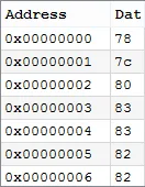
glTexImage2D(this->m_Target, 0, GL_LUMINANCE,
    this->m_PixelData.GetWidth(), this->m_PixelData.GetHeight(),
            0, GL_BGR, GL_UNSIGNED_BYTE, OFFSET_BUFFER(0));
像素缓冲区从以下内容开始:
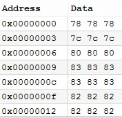
如果我以以下方式加载位移图(GL_RGB):
glTexImage2D(this->m_Target, 0, GL_RGB, this->m_PixelData.GetWidth(), this->m_PixelData.GetHeight(), 0, GL_BGR, GL_UNSIGNED_BYTE, OFFSET_BUFFER(0));
像素缓冲区从以下位置开始:
因此,我的问题似乎不是来自内存中加载的纹理。也许矩阵存在问题或者存在空间问题。我真的很迷失。
请问有人可以帮帮我吗?
非常感谢您提前的帮助!
textOffset方法是一个早期的方法,它做了一个非常大的近似:在偏移处的深度将是相同的。为了获得更好的效果,请跟踪(或“步进”)高度图直到找到交点。使用二分搜索来改进它。然后使用您的交点坐标进行着色。 - jozxyqkviewDir_TS只需要取反或者你的切线空间有问题。FragColor = vec4(viewDir_TS, 1);这样做会很有趣。 - jozxyqkglm::inverseTranspose(glm::mat3(modelViewMatrix)),尽管对于正交变换不会有影响。我认为在TBN之前可能已经转置了,因为列主构造的原因。 - jozxyqk