1个回答
5
这篇相关于IT技术的文章是2004年的,自那时以来graphviz已经进行了一些更改。以下是如何调整清单°1以显示源自记录形状单元格中心的边缘:
在定义边缘之前添加以下行:
为了使所有边缘起点和终点都在记录节点的中心:
在定义边缘之前添加以下行:
edge[headclip=false, tailclip=false];
这告诉graphviz在边缘节点处结束而不是裁剪它们。
但在这种情况下,这还不够,因为边缘已经使用了一个端口 - 我们可以添加一个罗盘点来指示边缘的末尾/开头应该放在哪里。例如,为了使第一条边从J的中心到E的边缘:
"node0":f1:c -> "node1":f1;
或者只需省略端口和方位,使用节点的中心:
"node0" -> "node1":f1;
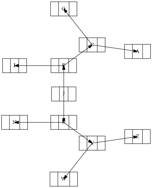
为了使所有边缘起点和终点都在记录节点的中心:
digraph G
{
    node [shape = record];
    edge[headclip=false, tailclip=false];

    node0 [ label ="<f0> | <f1> J | <f2> "];
    node1 [ label ="<f0> | <f1> E | <f2> "];
    node4 [ label ="<f0> | <f1> C | <f2> "];
    node6 [ label ="<f0> | <f1> I | <f2> "];
    node2 [ label ="<f0> | <f1> U | <f2> "];
    node5 [ label ="<f0> | <f1> N | <f2> "];
    node9 [ label ="<f0> | <f1> Y | <f2> "];
    node8 [ label ="<f0> | <f1> W | <f2> "];
    node10 [ label ="<f0> | <f1> Z | <f2> "];
    node7 [ label ="<f0> | <f1> A | <f2> "];
    node3 [ label ="<f0> | <f1> G | <f2> "];

    // identical result: "node0" -> "node1";
    "node0":f1:c -> "node1":f1:c;
    "node0":f1:c -> "node2":f1:c;

    "node1":f1:c -> "node4":f1:c;
    "node1":f1:c -> "node6":f1:c;
    "node4":f1:c -> "node7":f1:c;
    "node4":f1:c -> "node3":f1:c;

    "node2":f1:c -> "node5":f1:c;
    "node2":f1:c -> "node9":f1:c;

    "node9":f1:c -> "node8":f1:c;
    "node9":f1:c -> "node10":f1:c;
}
- marapet
1
谢谢,使用罗盘点和不剪裁尾部完美地解决了问题! - Herrmann
网页内容由stack overflow 提供, 点击上面的可以查看英文原文,
原文链接
原文链接