VHDL矩阵乘法

3
背景:我正在尝试创建一个用于三个矩阵相乘的行为文件。我试图通过首先查看是否可以读取输入矩阵,然后输出中间矩阵来调试它。
行为文件:
LIBRARY ieee;
USE ieee.std_logic_1164.ALL;

entity DCT_beh is
    port (
            Clk :           in std_logic;
            Start :         in std_logic;
            Din :           in INTEGER;
            Done :          out std_logic;
            Dout :          out INTEGER
          );
 end DCT_beh;

architecture behavioral of DCT_beh is 
begin
    process
            type RF is array ( 0 to 7, 0 to 7 ) of INTEGER;

            variable i, j, k        : INTEGER;
            variable InBlock        : RF;
            variable COSBlock       : RF;
            variable TempBlock      : RF;
            variable OutBlock       : RF;
            variable A, B, P, Sum   : INTEGER; 

    begin

            COSBlock := ( 
    ( 125,  122,    115,    103,    88,     69,     47,     24  ),
    ( 125,  103,    47,     -24,    -88,    -122,   -115,   -69  ),
    ( 125,  69,     -47,    -122,   -88,    24,     115,    103  ),
    ( 125,  24,     -115,   -69,    88,     103,    -47,    -122  ),
    ( 125,  -24,    -115,   69,     88,     -103,   -47,    122  ),
    ( 125,  -69,    -47,    122,    -88,    -24,    115,    -103  ),
    ( 125,  -103,   47,     24,     -88,    122,    -115,   69  ),
    ( 125,  -122,   115,    -103,   88,     -69,    47,     -24  )
                    );

--Starting
    wait until Start = '1';
        Done <= '0';

--Read Input Data
    for i in 0 to 7 loop
        for j in 0 to 7 loop    
            wait until Clk = '1' and clk'event;
            InBlock(i,j) := Din;
        end loop;
    end loop;

--TempBlock = COSBLOCK * InBlock 

    for i in 0 to 7 loop
        for j in 0 to 7 loop
            Sum := 0;
            for k in 0 to 7 loop
                A := COSBlock( i, k ); 
                B := InBlock( k, j ); 
                P := A * B; 
                Sum := Sum + P; 
                if( k = 7 ) then 
                TempBlock( i, j ) := Sum;
                end if;
            end loop;
        end loop;
    end loop;


--Finishing 

    wait until Clk = '1' and Clk'event;
    Done <= '1';

--Output Data

    for i in 0 to 7 loop
        for j in 0 to 7 loop
            wait until Clk = '1' and Clk'event;
            Done <= '0';
            Dout <=  tempblock(i,j);
        end loop;
    end loop;
end process;      
 end behavioral;

测试台文件:

LIBRARY ieee;
USE ieee.std_logic_1164.ALL;

-- Uncomment the following library declaration if using
-- arithmetic functions with Signed or Unsigned values
--USE ieee.numeric_std.ALL;

 ENTITY lab4b_tb IS
 END lab4b_tb;

ARCHITECTURE behavior OF lab4b_tb IS 

-- Component Declaration for the Unit Under Test (UUT)

COMPONENT DCT_beh
PORT(
     Clk : IN  std_logic;
     Start : IN  std_logic;
     Din : IN  INTEGER;
     Done : OUT  std_logic;
     Dout : OUT  INTEGER
    );
END COMPONENT;


   --Inputs
   signal Clk : std_logic := '0';
   signal Start : std_logic := '0';
   signal Din : INTEGER;

--Outputs
   signal Done : std_logic;
   signal Dout : INTEGER;

   -- Clock period definitions
   constant Clk_period : time := 10 ns;

 BEGIN

-- Instantiate the Unit Under Test (UUT)
   uut: DCT_beh PORT MAP (
      Clk => Clk,
      Start => Start,
      Din => Din,
      Done => Done,
      Dout => Dout
    );

   -- Clock process definitions
   Clk_process :process
   begin
    Clk <= '0';
    wait for Clk_period/2;
    Clk <= '1';
    wait for Clk_period/2;
  end process;


  -- Stimulus process
  stim_proc: process

variable i, j : INTEGER;
variable cnt : INTEGER;

  begin     
     -- hold reset state for 100 ns.

     wait for 100 ns;   

        start <= '1'; 
        wait for clk_period; 
        start <= '0';

    for cnt in 0 to 63 loop
        wait until clk = '1' and clk'event;
            din <= cnt;
        end loop;

        --wait for 100 ns;

        --start <= '1';
        --wait for clk_period;
        --start <= '0';

        --for i in 0 to 63 loop
          -- wait for clk_period;
            --if (i < 24) then
                --din <= 255;
            --elsif (i > 40) then
                --din <= 255;
            --else
                --din <= 0;
            --end if;
        --end loop;


  wait;
  end process;

END;

当start=1时,矩阵被读入inputblock。在这种情况下,矩阵仅填充了从0到63的唯一递增值。然后,当done=1时,输出乘积矩阵outblock。问题在于,在我的模拟中,我收到了一些应该在最终矩阵中但顺序不正确的值。例如,下面的行包含乘积矩阵tempblock中的第一行:

 14464.000  15157.000  15850.000  16543.000  17236.000  17929.000  18622.000  19315.000

作为我的模拟图中所示,我获得了一些值,但是信号变成了一些奇怪的大值。
我有一些疑问,din(0), din(1), din(2)...din(n) 是否与 inputblock(0,0),inputblock(0,1),inputblock(0,2) 等相对应。但是我仔细检查了我的行为文件,并没有发现任何问题。我的测试台设计有什么问题吗?
编辑:我需要在此输出结果。
        din<=0;


    for i in 0 to 63 loop
        wait until clk = '1' and clk'event;
        if i = 0 then
            Start <= '1','0' after clk_period;
            end if;
            if (i < 24) then
                din <= 255;
            elsif (i > 40) then
                din <= 255;
            else
                din <= 0;
            end if;

    end loop;

我原以为这段代码与答案中的代码类似,但我遇到了完全相同的问题。如何解决?这是当前输出的图片。正确的值都在那里,只是被一个时钟周期向后移动了一个位置。 enter image description here 
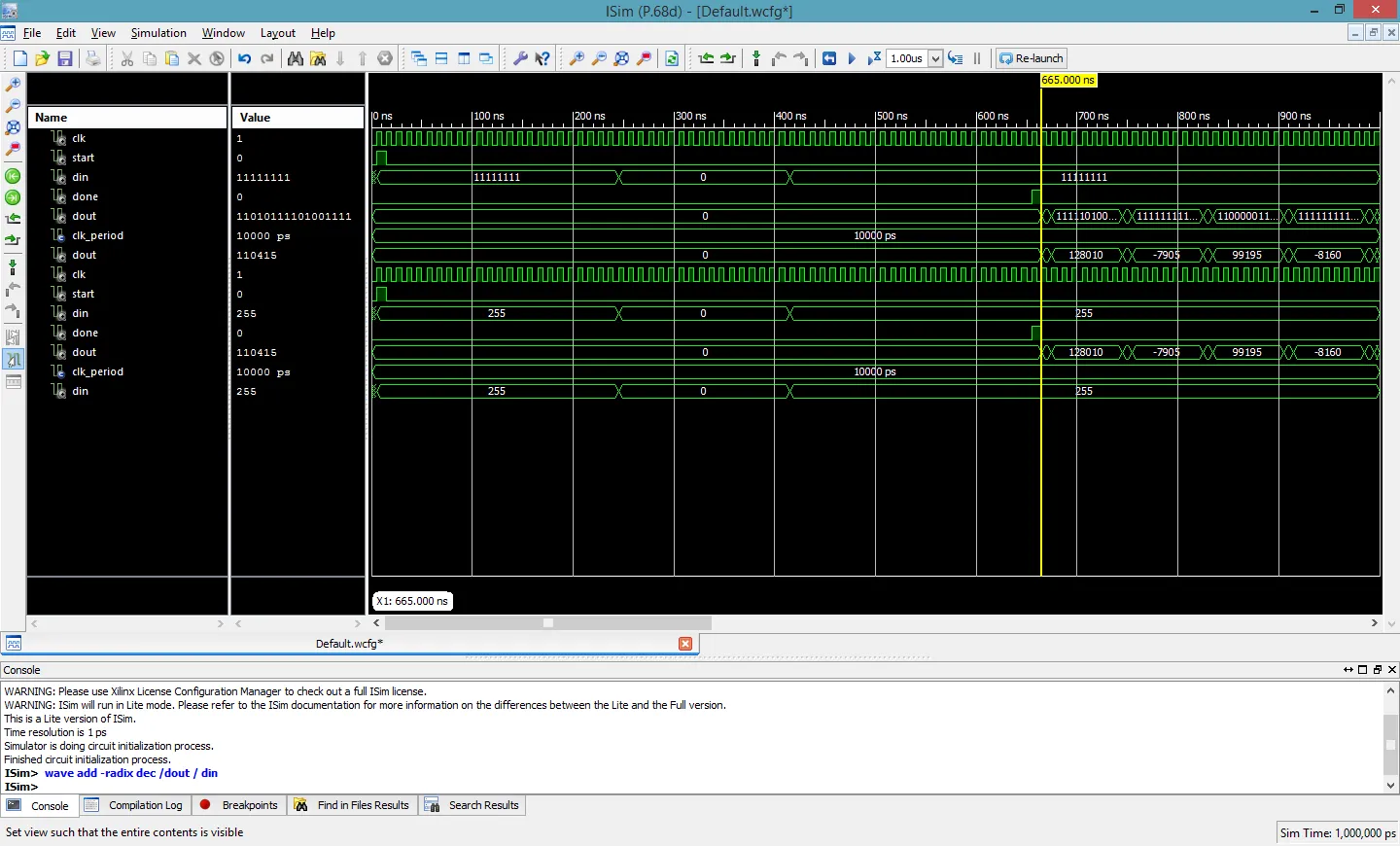
最终编辑:我自己解决了这个问题。问题出在循环边界上。

1
是否不可能大或者是负数? - user1155120
与结果矩阵中的其他值相比,它似乎非常大。第一个[0][0]值出现在前两个时钟周期之后。这让我相信时序有些偏差,导致整个输出块显示不正确。 - user1766888
我没有一个可以将非信号输出到波形的模拟器。你所说的两个时钟延迟似乎是在DCT_beh中的--Finishing和--Output Data注释之后。DONE发生在一个时钟后,然后另一个时钟开始输出数据。尝试组合Input Data和COSBlock * InBlock循环,你需要移动时钟等待。最终,Output Data循环也应该被合并进来。 - user1155120
现在你会意识到,你可以在一个时钟周期内对向量进行矩阵乘法。你需要一些东西来告诉使用输出数据的任何内容,在什么时候它是有效的。 - user1155120
输入端和输出端只通过它们的寄存器文件与转换器通信。当最后一个数据输入被加载时,开始进行转换,将输入切换到填充下一组。当转换完成后,它会被转储到一个输出寄存器文件中,并发出管道输出有效的信号,对于那64个输出而言。因此,有一个输入完成和一个输出可用或准备好的信号。每个人都知道要传输64个数据值。 - user1155120
显示剩余5条评论
1个回答

2

这里是一个看起来可行的模型和测试台版本

添加了(并更新)

如果您将矩阵乘法变成实时(时钟),您会看到DONE延迟了执行矩阵乘法所需的时钟数。我随意选择了两个时钟,只是为了展示添加寄存器文件的好处。

我将对代码中有趣的部分进行评论。

LIBRARY ieee;
USE ieee.std_logic_1164.ALL;

 ENTITY lab4b_tb IS
 END lab4b_tb;

ARCHITECTURE behavior OF lab4b_tb IS 

   signal Clk:      std_logic   := '0';  -- no reset
   signal Start:    std_logic   := '0';  -- no reset
   signal Din:      INTEGER     := 0;     -- no reset

   signal Done : std_logic;
   signal Dout : INTEGER;

   constant Clk_period : time := 10 ns;

BEGIN

   uut: entity work.DCT_beh -- DCT_beh 
       PORT MAP (
           Clk => Clk,
           Start => Start,
           Din => Din,
           Done => Done,
           Dout => Dout
      );

CLOCK: 
    process
    begin
        Clk <= '0';
        wait for Clk_period/2;
        Clk <= '1';
        wait for Clk_period/2;
    end process;

STIMULUS: 
    process
        variable i, j : INTEGER;
        variable cnt : INTEGER;
    begin     

         wait until clk = '1' and clk'event;  -- sync Start to clk

FIRST_BLOCK_IN:
        Start <= '1','0' after 11 ns;  --issued same time as datum 0
        for i in 0 to 63 loop
                if (i < 24) then
                    din <= 255;
                elsif (i > 40) then
                    din <= 255;
                else
                    din <= 0;
                end if;
                wait until clk = '1' and clk'event;
        end loop;
SECOND_BLOCK_N:
        Start <= '1','0' after 11 ns;  -- with first datum
        for cnt in 0 to 63 loop
            din <= cnt; 
            wait until clk = '1' and clk'event;
        end loop;
        din <= 0;  -- to show the last input datum clearly

        wait;
    end process;

END ARCHITECTURE;

两个输入块分别为新的块值和原始块值,可为第一个输出块提供索引。第二个块也显示了与最初相同的答案,验证了已完成的握手。
注意:开始注释是与每个块的第一个数据同时进行的。
我还调整了输入刺激以从时钟边界开始,以避免第一个开始出现在时钟下降沿上。
当异步生成脉冲存在时,我将它们扩展了一纳秒以确保它们可以在时钟边缘上被观察到,因为它们不是在时钟边缘上生成的。
LIBRARY ieee;
USE ieee.std_logic_1164.ALL;

entity DCT_beh is
    port (
        Clk :           in std_logic;
        Start :         in std_logic;
        Din :           in INTEGER;
        Done :          out std_logic;
        Dout :          out INTEGER
      );

 end DCT_beh;

architecture behavioral of DCT_beh is 
    type RF is array ( 0 to 7, 0 to 7 ) of INTEGER;
    signal OutBlock:            RF;
    signal InBlock:             RF;
    signal internal_Done:       std_logic := '0';  -- no reset
    signal Input_Ready:         std_logic := '0';  -- no reset
    signal done_detected:       std_logic := '0';  -- no reset
    signal input_rdy_detected:  std_logic := '0';  -- no reset
    signal last_out:            std_logic := '0';  -- no reset

begin
INPUT_DATA:
    process
    begin
        wait until Start = '1';
        --Read Input Data
        for i in 0 to 7 loop
            for j in 0 to 7 loop    
                wait until Clk = '1' and clk'event;
                InBlock(i,j) <= Din;
                if i=7 and j=7 then
                    Input_Ready <= '1', '0' after 11 ns;  
                end if;
            end loop;
        end loop;
    end process;

WAIT_FOR_InBlock:
    process
    begin   
        wait until clk = '1' and clk'event;
        input_rdy_detected <= Input_Ready;  
        --InBlock valid after the following rising edge of clk
    end process;

TRANSFORM:
    process 
            variable InpBlock       : RF;
            constant COSBlock       : RF :=
            ( 
                ( 125,   122,   115,    103,    88,     69,     47,      24  ),
                ( 125,   103,    47,    -24,   -88,   -122,   -115,     -69  ),
                ( 125,    69,   -47,   -122,   -88,     24,    115,     103  ),
                ( 125,    24,  -115,    -69,    88,    103,    -47,    -122  ),
                ( 125,   -24,  -115,     69,    88,   -103,    -47,     122  ),
                ( 125,   -69,   -47,    122,   -88,    -24,    115,    -103  ),
                ( 125,  -103,    47,     24,   -88,    122,   -115,      69  ),
                ( 125,  -122,   115,   -103,    88,    -69,     47,     -24  )
            );
            variable TempBlock      : RF;
            variable A, B, P, Sum   : INTEGER; 
    begin

        if input_rdy_detected = '0' then
            wait until input_rdy_detected = '1';
        end if;

        InpBlock := InBlock;  -- Broadside dump or swap

--TempBlock = COSBLOCK * InBlock  

-- arbitrarily make matrix multiple 2 clocks long      
      wait until clk = '1' and clk'event;  -- 1st xfm clock

        for i in 0 to 7 loop
            for j in 0 to 7 loop
                Sum := 0;
                for k in 0 to 7 loop
                    A := COSBlock( i, k ); 
                    B := InpBlock( k, j ); 
                    P := A * B; 
                    Sum := Sum + P; 
                    if( k = 7 ) then 
                        TempBlock( i, j ) := Sum;
                    end if;
                end loop;
            end loop;
        end loop;

  --  Done issued in clk cycle of last TempBlock( i, j )  := Sum;

        internal_Done <= '1', '0' after 11 ns;  
        wait until clk = '1' and clk'event;  -- 2nd xfrm clk   
        -- OutBlock available after last TempBlock value stored   

        OutBlock <= TempBlock;   -- Broadside dump or swap
    end process;

Done_BUFFER:
    Done <= internal_Done;


WAIT_FOR_OutBlock:
    process
    begin
        wait until clk = '1' and clk'event;
        done_detected <= internal_Done;
        -- Done can come either before the first output_data transfer
        -- or during the last output data transfer
        -- this gives us the clock delay to finish the last xfm transfer to 
        -- TempBlock( i, j)
        -- Technically part of the output process but was too cumbersome to write
    end process;

OUTPUT_DATA:
    process
    begin
        -- OutBlock is valid after clock edge when Done is true
        for i in 0 to 7 loop
            for j in 0 to 7 loop

                if i = 0 and j = 0 then

                    if done_detected = '0' then
                        wait until done_detected = '1';
                    end if; 
                end if;  

                Dout <=  OutBlock(i,j);                        
                wait until clk = '1' and clk'event;
            end loop;
        end loop;
    end process;

end behavioral;

RF的类型定义已经被移动到架构声明部分,以允许通过信号进行进程间通信。输入循环,矩阵乘法和输出循环都在自己的进程中。我还添加了用于进程间握手的过程(Input_Ready和input_Done(Done),添加了input_rdy_detect和done_detect信号。
如果一个进程可以花费64个时钟周期,那么显示最后一个数据处理过程(Input_Ready和潜在的Done)的信号将在下游进程的最后一个数据事务期间施加。否则编码会非常混乱,你仍然需要触发器。
在输入过程和乘法过程之间添加了RF,以允许并发操作,当矩阵乘法需要实时运行时(在这个例子中需要2个时钟周期,我不想把波形拉得太远)。
一些握手延迟似乎与编码风格有关,并且使用input_rdy_detect和done_detect触发器进行了修复。
第一个波形图显示了在变换过程现在需要的两个时钟周期之后的第一个输出数据,显示在A和B标记之间。
你可以看到,在Done之后立即出现的第一个输出数据是78540,而不是你的波形屏幕截图中显示的110415。我们其中一个显示的值是错误的。这个DCT_beh版本严格执行仅在最后一个数据加载后传输RF值的规定。
在清理输入过程和乘法过程之间的握手之前,我确实得到了110415的值。要跟踪它穿过TempBlock和OutBlock将需要很多工作。
现在是好消息。第二个输入块取自您原始的刺激,并且输入值对于输出转移来说是一个很好的索引。这些输出数据值都是正确的。
input_rdy_detect和done_detect信号恰好显示其各自下游进程中的第一个事务。我添加了一个trailing din信号分配为0,避免在第二个输入块结束时混淆。
这里是一个近似你的屏幕截图,我不能选择缩放,而是使用连续逼近。
只需运行仿真到1955 ns即可捕获第二个块的最后一个数据输出。
这是在运行OS X 10.8.4的Mac上使用Tristan Gingold的ghdl和Tony Bybell的gtkwave完成的。

谢谢你的回答。你知道我怎么能改变上面的编辑代码吗?我有完全相同的问题,但是使用了不同的指令集。 - user1766888
我编辑了你的模型,将其操作分为三个状态,并在单独的进程中运行。据我所知,这样做至少需要一个时钟(模拟Done周期与寄存器文件的最后一次写入同义)。因此,我添加了第二个时钟以显示边界工作情况。 - user1155120

网页内容由stack overflow 提供, 点击上面的
可以查看英文原文,
原文链接