Gnuplot多图层3D数据可视化排序

4

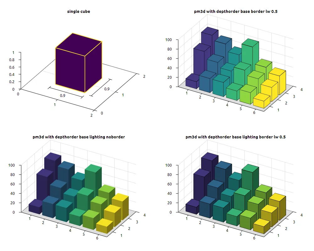
参考 gnuplotting 的示例,我试图创建一个三维柱状图,如下所示:respects depthorder
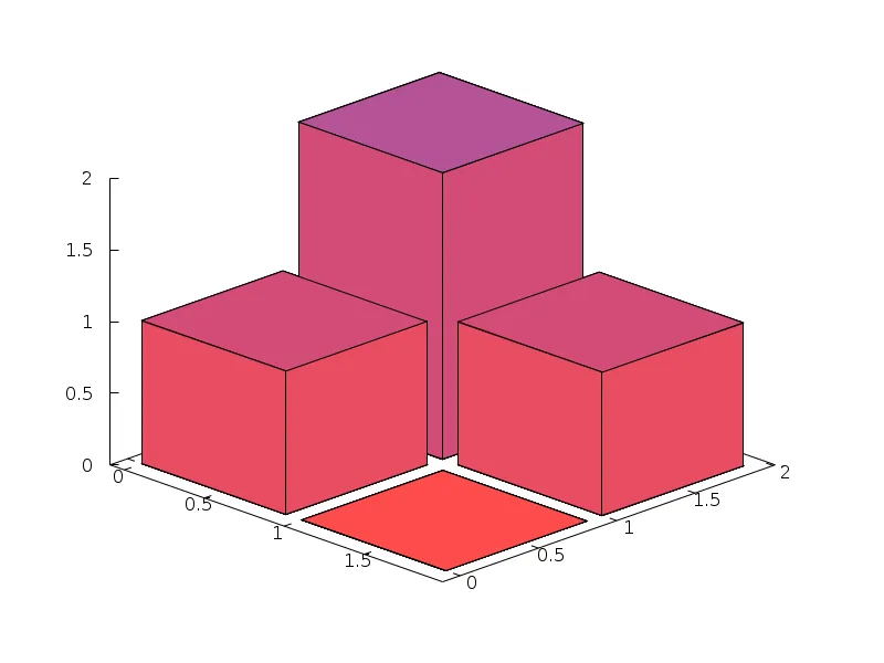
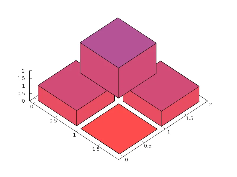
但是,在高角度视图下,depthorder 并不能得到保持: does not respect depthorder

生成这些图的 gnuplot 命令(版本 5.2)如下:

set terminal pngcairo  enhanced  size 800,600 
set output "cube_depthorder.png"
set cbrange [0:10] 
set palette defined ( 1 '#ff4c4d', 2 '#ce4c7d', 3 '#ae559e', 4 '#df866d', 5 '#ffb66d', 6 '#ffe7cf', 7 '#cecece', 8 '#6d6d6d', 9 '#4c4c8e', 10 '#4c4cef' )
set view 60,45,1,1
set xrange [-0.09:1.99] 
set xyplane at 0
set yrange [-0.1125:2.0125] 
set pm3d at s depthorder border
unset colorbox
splot   "-" binary record=(5,4) format="%double%double%double"   using 1:2:3 notitle with lines  dt solid  linecolor  rgb  "black "  ,   "-" binary record=(5,4) format="%double%double%double"   using 1:2:3 notitle with lines  dt solid  linecolor  rgb  "black "  ,   "-" binary record=(5,4) format="%double%double%double"   using 1:2:3 notitle with lines  dt solid  linecolor  rgb  "black "  ,   "-" binary record=(5,4) format="%double%double%double"   using 1:2:3 notitle with lines  dt solid  linecolor  rgb  "black "  

如上所述,splot命令包含四个条目。在将它们发送到splot之前,我已经尝试将这些条目按从高到矮的顺序排序,但是这对depthorder没有任何影响。
我怀疑depthorder通过从四边形中心到绘图视口测量距离并按距离排序来排序。然后有一个角度,高的四边形中心比矮的四边形中心更靠近,因此会以不同的顺序绘制。 这个怀疑正确吗?或者还有其他问题?在这种情况下,有没有解决方案可以“正确地”测量depthorder 对于那些希望重新创建这些图表的人,这里有一个包含等值线的数据文件(每行都是五个(x,y,z)点,每个立方体有4行(2个水平和2个垂直),共四个立方体)。

0 1 0 
0 1.9 0 
0 1.9 2 
0 1 2 
0 1 0 

1 1 0 
1 1.9 0 
1 1.9 1 
1 1 1 
1 1 0 

0 0 0 
0 0.9 0 
0 0.9 1 
0 0 1 
0 0 0 

1 0 0 
1 0.9 0 
1 0.9 0 
1 0 0 
1 0 0 


0.9 1 0 
0.9 1.9 0 
0.9 1.9 2 
0.9 1 2 
0.9 1 0 

1.9 1 0 
1.9 1.9 0 
1.9 1.9 1 
1.9 1 1 
1.9 1 0 

0.9 0 0 
0.9 0.9 0 
0.9 0.9 1 
0.9 0 1 
0.9 0 0 

1.9 0 0 
1.9 0.9 0 
1.9 0.9 0 
1.9 0 0 
1.9 0 0 


0 1 0 
0 1.9 0 
0.9 1.9 0 
0.9 1 0 
0 1 0 

1 1 0 
1 1.9 0 
1.9 1.9 0 
1.9 1 0 
1 1 0 

0 0 0 
0 0.9 0 
0.9 0.9 0 
0.9 0 0 
0 0 0 

1 0 0 
1 0.9 0 
1.9 0.9 0 
1.9 0 0 
1 0 0 


0 1 2 
0 1.9 2 
0.9 1.9 2 
0.9 1 2 
0 1 2 

1 1 1 
1 1.9 1 
1.9 1.9 1 
1.9 1 1 
1 1 1 

0 0 1 
0 0.9 1 
0.9 0.9 1 
0.9 0 1 
0 0 1 

1 0 0 
1 0.9 0 
1.9 0.9 0 
1.9 0 0 
1 0 0 

2个回答

6
在gnuplot的开发版本中,类似于3D箱线图的绘制方式已经被支持。请参考以下在线示例: http://gnuplot.sourceforge.net/demo_5.3/3dboxes.html。 要使此方法奏效的关键是必须按照基准面上的z值对盒子的面进行排序。这个方法已经在新命令变量中实现: set pm3d depthorder base。 我不知道在早期版本的gnuplot中有任何正确的方法来实现这一点。

2
我知道这是一个老问题,但受到相同的gnuplotting条目的启发,我决定尝试一些真正适用于gnuplot 5.2.7的东西。这实际上是一个概念验证!即使使用depthorder base,只有按照特定顺序创建立方体面才能实现正确的z顺序。
为了说明这一点,我使用以下数据文件来绘制"立方体"
0.1 0.1 0.0
0.9 0.1 0.0
0.9 0.1 1.0
0.1 0.1 1.0
0.1 0.1 0.0

0.9 0.1 0.0
0.9 0.9 0.0
0.9 0.9 1.0
0.9 0.1 1.0
0.9 0.1 0.0

0.9 0.1 1.0
0.9 0.9 1.0
0.1 0.9 1.0
0.1 0.1 1.0
0.9 0.1 1.0

0.9 0.1 0.0
0.9 0.9 0.0
0.1 0.9 0.0
0.1 0.1 0.0
0.9 0.1 0.0

使用以下代码...

reset
set terminal pngcairo font "Ubuntu,10" size 1000,800
set output "3D_Graph.png"
set tics out nomirror
unset key
set xyplane at 0
unset colorbox

set arrow 1 from 0.55,0.40,0 to 1.45,0.4,0 nohead
set arrow 2 from 0.55,0.32,0 to 0.55,0.47,0 nohead
set arrow 3 from 1.45,0.32,0 to 1.45,0.47,0 nohead

set arrow 4 from 1.60,0.55,0 to 1.60,1.45,0 nohead
set arrow 5 from 1.55,0.55,0 to 1.65,0.55,0 nohead
set arrow  from 1.55,1.45,0 to 1.65,1.45,0 nohead

set style textbox opaque noborder fillcolor rgb "white"
set label 1 "0.9" at 0.95,0.2,0.0 boxed
set label 2 "0.9" at 1.70,1.0,0.0 boxed

set style line  1 lw 1.5 lc rgb "#fde725" 

# viridis colormap
set palette defined(\
    1 "#440154",\
    2 "#472c7a",\
    3 "#3b518b",\
    4 "#2c718e",\
    5 "#21908d",\
    6 "#27ad81",\
    7 "#5cc863",\
    8 "#aadc32",\
    9 "#fde725"\
)
# ================================================================================
set multiplot layout 2,2
set xtics 1
set ytics 1
set view equal xyz
set view ,,1.5,1
set cbrange [0:1]
set grid ls -1 lc "gray"
set pm3d depthorder hidden3d
set pm3d implicit
unset hidden3d
set title "{/:Bold single cube}"

splot [0:2][0:2][0:1] "cube_points.dat" u ($1+0.5):($2+0.5):($3):(0) w l ls 1
unset for [i=1:6] arrow i
unset for [i=1:2] label i
# --------------------------------------------------------------------------------
set grid xtics ytics ztics vertical layerdefault ls -1 lc "gray"
set view equal xy
set view ,,1.75,0.55
set xrange [0.25:6.6]
set yrange [0.25:4.0]
set zrange [0:100]
set ztics 20
set cbrange [0:*]

set object polygon from \
    graph 0, 0, 0 to \
    graph 1, 0, 0 to \
    graph 1, 1, 0 to \
    graph 0, 1, 0 to \
    graph 0, 0, 0 fc rgb "gray" fs transparent solid 0.50 noborder

set pm3d depthorder base border lw 0.5
set title "{/:Bold pm3d with depthorder base border lw 0.5}"

splot \
    "cube_points.dat" u ($1+0.5):($2+0.5):($3*15):(1) w pm3d,\
    "cube_points.dat" u ($1+0.5):($2+1.5):($3*65):(1) w pm3d,\
    "cube_points.dat" u ($1+0.5):($2+2.5):($3*85):(1) w pm3d,\
    "cube_points.dat" u ($1+1.5):($2+0.5):($3*30):(2) w pm3d,\
    "cube_points.dat" u ($1+1.5):($2+2.5):($3*75):(2) w pm3d,\
    "cube_points.dat" u ($1+1.5):($2+1.5):($3*50):(2) w pm3d,\
    "cube_points.dat" u ($1+2.5):($2+0.5):($3*30):(3) w pm3d,\
    "cube_points.dat" u ($1+2.5):($2+1.5):($3*40):(3) w pm3d,\
    "cube_points.dat" u ($1+2.5):($2+2.5):($3*60):(3) w pm3d,\
    "cube_points.dat" u ($1+3.5):($2+0.5):($3*20):(4) w pm3d,\
    "cube_points.dat" u ($1+3.5):($2+1.5):($3*50):(4) w pm3d,\
    "cube_points.dat" u ($1+3.5):($2+2.5):($3*85):(4) w pm3d,\
    "cube_points.dat" u ($1+4.5):($2+0.5):($3*25):(5) w pm3d,\
    "cube_points.dat" u ($1+4.5):($2+1.5):($3*40):(5) w pm3d,\
    "cube_points.dat" u ($1+4.5):($2+2.5):($3*50):(5) w pm3d,\
    "cube_points.dat" u ($1+5.5):($2+0.5):($3*15):(6) w pm3d,\
    "cube_points.dat" u ($1+5.5):($2+1.5):($3*30):(6) w pm3d,\
    "cube_points.dat" u ($1+5.5):($2+2.5):($3*40):(6) w pm3d

# --------------------------------------------------------------------------------

set pm3d depthorder base lighting noborder
set title "{/:Bold pm3d with depthorder base lighting noborder}"
replot

# --------------------------------------------------------------------------------

set pm3d depthorder base lighting border lw 0.5
set title "{/:Bold pm3d with depthorder base lighting border lw 0.5}"
replot
unset multiplot

我能够实现以下结果:

使用gnuplot绘制的3D箱形图

即使在高角度视图下也可以正常工作:

3D水平旋转

3D垂直旋转

当然,这段代码不能读取 x y z 类型的数据文件或创建 3D 聚类条形图,但它是一个开始。


注:Original Answer 翻译成“最初的回答”。

太棒了。我很快就会试一下。 - cms

网页内容由stack overflow 提供, 点击上面的
可以查看英文原文,
原文链接