编辑:您可能想从“编辑3”开始,因为我已经解决了很多问题
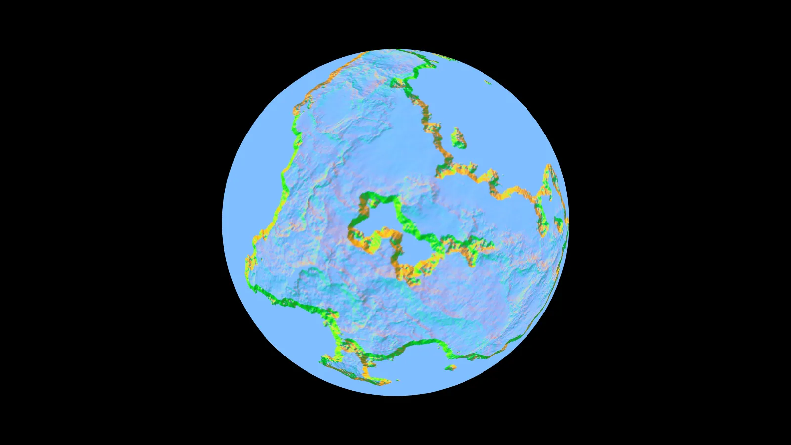
这是一个将我的普通立方体贴图应用于一个二十面体的截图:
m_indices 是指向 m_vertices 中的顶点的std::vector索引的std::vector。std::vector<glm::vec3> storedTan(m_vertices.size(),glm::vec3(0,0,0));
// tangents
for(int i = 0; i < m_indices.size(); i+=3)
{
int i1 = m_indices[i];
int i2 = m_indices[i+1];
int i3 = m_indices[i+2];
VertexData v1 = m_vertices[i1];
VertexData v2 = m_vertices[i2];
VertexData v3 = m_vertices[i3];
glm::vec3 p1 = glm::vec3(v1.position[0],v1.position[1],v1.position[2]);
glm::vec3 p2 = glm::vec3(v2.position[0],v2.position[1],v2.position[2]);
glm::vec3 p3 = glm::vec3(v3.position[0],v3.position[1],v3.position[2]);
glm::vec3 t1 = glm::vec3(v1.tcoords[0],v1.tcoords[1],v1.tcoords[2]);
glm::vec3 t2 = glm::vec3(v2.tcoords[0],v2.tcoords[1],v2.tcoords[2]);
glm::vec3 t3 = glm::vec3(v3.tcoords[0],v3.tcoords[1],v3.tcoords[2]);
std::function<glm::vec2(glm::vec3)> get_uv = [=](glm::vec3 STR)
{
float sc, tc, ma;
float x = std::abs(STR.x);
float y = std::abs(STR.y);
float z = std::abs(STR.z);
if(x > y && x > z)
{
if(STR.x > 0)
{
sc = -STR.z;
tc = -STR.y;
ma = STR.x;
}
else
{
sc = STR.z;
tc = -STR.t;
ma = STR.x;
}
}
else if(y > z)
{
if(STR.y > 0)
{
sc = STR.x;
tc = STR.z;
ma = STR.y;
}
else
{
sc = STR.x;
tc = -STR.z;
ma = STR.y;
}
}
else
{
if(STR.z > 0)
{
sc = STR.x;
tc = -STR.y;
ma = STR.z;
}
else
{
sc = -STR.x;
tc = -STR.y;
ma = STR.z;
}
}
return glm::vec2((sc/std::abs(ma) + 1.0) / 2.0,(tc/std::abs(ma) + 1.0) / 2.0);
};
glm::vec2 uv1 = get_uv(t1);
glm::vec2 uv2 = get_uv(t2);
glm::vec2 uv3 = get_uv(t3);
glm::vec3 edge1 = p2 - p1;
glm::vec3 edge2 = p3 - p1;
glm::vec2 tedge1 = uv2 - uv1;
glm::vec2 tedge2 = uv3 - uv1;
float r = 1.0f / (tedge1.x * tedge2.y - tedge2.x - tedge1.y);
glm::vec3 sdir((tedge2.y * edge1.x - tedge1.y * edge2.x) * r,
(tedge2.y * edge1.y - tedge1.y * edge2.y) * r,
(tedge2.y * edge1.z - tedge1.y * edge2.z) * r);
glm::vec3 tdir((tedge1.x * edge2.x - tedge2.x * edge1.x) * r,
(tedge1.x * edge2.y - tedge2.x * edge1.y) * r,
(tedge1.x * edge2.z - tedge2.x * edge1.z) * r);
m_vertices[i1].tangent[0] += sdir.x;
m_vertices[i1].tangent[1] += sdir.y;
m_vertices[i1].tangent[2] += sdir.z;
m_vertices[i2].tangent[0] += sdir.x;
m_vertices[i2].tangent[1] += sdir.y;
m_vertices[i2].tangent[2] += sdir.z;
m_vertices[i3].tangent[0] += sdir.x;
m_vertices[i3].tangent[1] += sdir.y;
m_vertices[i3].tangent[2] += sdir.z;
storedTan[i1] += sdir;
storedTan[i2] += sdir;
storedTan[i3] += sdir;
}
for(int i = 0; i < m_vertices.size(); ++i)
{
glm::vec3 n = glm::vec3(m_vertices[i].normal[0],m_vertices[i].normal[1],m_vertices[i].normal[2]);
glm::vec3 t = glm::vec3(m_vertices[i].tangent[0],m_vertices[i].tangent[1],m_vertices[i].tangent[2]);
glm::vec3 newT = glm::normalize(t - n * glm::dot(n,t));
m_vertices[i].tangent[0] = newT.x;
m_vertices[i].tangent[1] = newT.y;
m_vertices[i].tangent[2] = newT.z;
m_vertices[i].tangent[3] = (glm::dot(glm::cross(n,t), storedTan[i]) < 0.0f) ? -1.0f : 1.0f;
}
顺便说一下,我的VertexData看起来像这样:
struct VertexData
{
    GLfloat position[4];
    GLfloat normal[3];
    GLfloat tcoords[3];
    GLfloat tangent[4];
};
我知道当前的
tcoords、position和normal都很好(否则你就看不到上面的截图了)。然后我的顶点着色器看起来像这样:
#version 400

layout (location = 0) in vec4 in_position;
layout (location = 1) in vec3 in_normal;
layout (location = 2) in vec3 in_UV;
layout (location = 3) in vec4 in_tangent;

struct PointLight
{
    bool active;

    vec3 position;
    vec3 ambient;
    vec3 diffuse;
    vec3 specular;

    float constant;
    float linear;
    float quadratic;
};

uniform mat4 model;
uniform mat4 view;
uniform mat4 projection;
uniform mat4 lightMVP;

uniform PointLight uLight;

smooth out vec3 ex_UV;
out vec3 ex_normal;
out vec3 ex_positionCameraSpace;
out vec3 ex_originalPosition;
out vec3 ex_positionWorldSpace;
out vec4 ex_positionLightSpace;
out vec3 ex_tangent;
out vec3 ex_binormal;

out PointLight ex_light;

void main()
{
    gl_Position = projection * view * model * in_position;

    ex_UV = in_UV;
    ex_normal = mat3(transpose(inverse(view * model))) * in_normal;
    ex_positionCameraSpace =  vec3(view * model * in_position);
    ex_originalPosition = vec3(in_position.xyz);
    ex_positionWorldSpace = vec3(model*in_position);
    ex_positionLightSpace = lightMVP * model * in_position;

    ex_tangent = mat3(transpose(inverse(view * model))) * in_tangent.xyz;
    ex_binormal = cross(ex_normal,ex_tangent);

    // provide the fragment shader with a light in view space rather than world space
    PointLight p = uLight;
    p.position = vec3(view * vec4(p.position,1.0));
    ex_light = p;
}
最后,我的片段着色器看起来像这样:
#version 400

layout (location = 0) out vec4 color;

struct Material
{
    bool useMaps;
    samplerCube diffuse;
    samplerCube specular;
    samplerCube normal;
    float shininess;
    vec4 color1;
    vec4 color2;
};

struct PointLight
{
    bool active;

    vec3 position;
    vec3 ambient;
    vec3 diffuse;
    vec3 specular;

    float constant;
    float linear;
    float quadratic;
};

uniform Material uMaterial;

smooth in vec3 ex_UV;
in vec3 ex_normal;
in vec3 ex_positionCameraSpace;
in vec3 ex_originalPosition;
in vec3 ex_positionWorldSpace;
in vec4 ex_positionLightSpace;

in vec3 ex_tangent;
in vec3 ex_binormal;

in PointLight ex_light;

/* ******************
Provides a better lookup into a cubemap
******************* */
vec3 fix_cube_lookup(vec3 v, float cube_size)
{
    float M = max(max(abs(v.x), abs(v.y)), abs(v.z));
    float scale = (cube_size - 1) / cube_size;
    if (abs(v.x) != M)
        v.x *= scale;
    if (abs(v.y) != M)
        v.y *= scale;
    if (abs(v.z) != M)
        v.z *= scale;
    return v;
}

/* *********************
Calculates the color when using a point light. Uses shadow map
********************* */
vec3 CalcPointLight(PointLight light, Material mat, vec3 normal, vec3 fragPos, vec3 originalPos, vec3 viewDir)
{
    // replace the normal with lookup normal. This is now in tangent space
    vec3 textureLookup = fix_cube_lookup(normalize(ex_originalPosition),textureSize(mat.normal,0).x);
    normal = texture(mat.normal,textureLookup).rgb;

    // the direction the light is in in the light position - fragpos
    // light dir and view dir are now in tangent space
    vec3 lightDir = transpose(mat3(ex_tangent,ex_binormal,ex_normal)) * normalize(fragPos - light.position);
    viewDir = transpose(mat3(ex_tangent,ex_binormal,ex_normal)) * viewDir;

    // get the diffuse color
    textureLookup = fix_cube_lookup(normalize(ex_originalPosition),textureSize(mat.diffuse,0).x);
    vec3 diffuseMat = vec3(0.0);
    if(mat.useMaps)
        diffuseMat = texture(mat.diffuse,textureLookup).rgb;
    else
        diffuseMat = mat.color1.rgb;

    // get the specular color
    textureLookup = fix_cube_lookup(normalize(ex_originalPosition),textureSize(mat.specular,0).x);
    vec3 specularMat = vec3(0.0);
    if(mat.useMaps)
        specularMat = texture(mat.specular,textureLookup).rgb;
    else
        specularMat = mat.color2.rgb;

    // the ambient color is the amount of normal ambient light hitting the diffuse texture
    vec3 ambientColor = light.ambient * diffuseMat;

    // Diffuse shading
    float diffuseFactor = dot(normal, -lightDir);
    vec3 diffuseColor = vec3(0,0,0);
    vec3 specularColor = vec3(0,0,0);
    if(diffuseFactor > 0)
        diffuseColor = light.diffuse * diffuseFactor * diffuseMat;

    // Specular shading
    vec3 reflectDir = normalize(reflect(lightDir, normal));
    float specularFactor = pow(dot(viewDir,reflectDir), mat.shininess);
    if(specularFactor > 0 && diffuseFactor > 0)
        specularColor = light.specular * specularFactor * specularMat;

    float lightDistance = length(fragPos - light.position);
    float attenuation = light.constant + light.linear * lightDistance + light.quadratic * lightDistance * lightDistance;

    return ambientColor + (diffuseColor + specularColor) / attenuation;
}

void main(void)
{
    vec3 norm = normalize(ex_normal);
    vec3 viewDir = normalize(-ex_positionCameraSpace);

    vec3 result = CalcPointLight(ex_light,uMaterial,norm,ex_positionCameraSpace, ex_positionWorldSpace,viewDir);

    color = vec4(result,1.0);
}
据我所知:
- 我的正切线计算正确。
- 我的法线贴图看起来像一张法线贴图。
- 我将光照和视角方向改为正切空间以匹配我的法线贴图。
如果我放弃查找我的法线贴图,而是使用正切矩阵的光照和视角,我会得到以下结果:
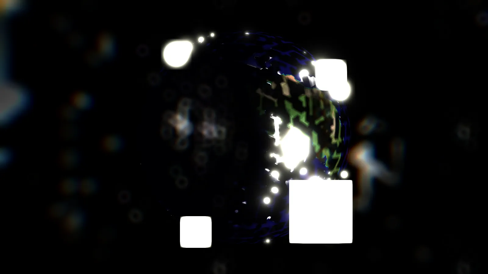
如果我只是通过切线矩阵转换光线,我会得到这个:
所有这些都告诉我,我不知道哪里出错了。
我有一个想法,那就是我的正切生成可能有问题,因为其他部分似乎遵循我阅读的每个教程所说的。正切是根据以立方体贴图的icosphere为基础生成的。因此,为了确定从cubemaps通常的3D坐标到<S,T>或<U,V> 2D坐标,我:
- 使用最大值来确定我所在的面
- 使用https://www.opengl.org/registry/specs/ARB/texture_cube_map.txt中的代码来确定S、T坐标
这是我所说的https://www.opengl.org/registry/specs/ARB/texture_cube_map.txt的摘录。
  major axis
  direction     target                             sc     tc    ma
  ----------    -------------------------------    ---    ---   ---
   +rx          TEXTURE_CUBE_MAP_POSITIVE_X_ARB    -rz    -ry   rx
   -rx          TEXTURE_CUBE_MAP_NEGATIVE_X_ARB    +rz    -ry   rx
   +ry          TEXTURE_CUBE_MAP_POSITIVE_Y_ARB    +rx    +rz   ry
   -ry          TEXTURE_CUBE_MAP_NEGATIVE_Y_ARB    +rx    -rz   ry
   +rz          TEXTURE_CUBE_MAP_POSITIVE_Z_ARB    +rx    -ry   rz
   -rz          TEXTURE_CUBE_MAP_NEGATIVE_Z_ARB    -rx    -ry   rz

 Using the sc, tc, and ma determined by the major axis direction as
 specified in the table above, an updated (s,t) is calculated as
 follows

    s   =   ( sc/|ma| + 1 ) / 2
    t   =   ( tc/|ma| + 1 ) / 2

 This new (s,t) is used to find a texture value in the determined
 face's 2D texture image using the rules given in sections 3.8.5
 and 3.8.6." ...
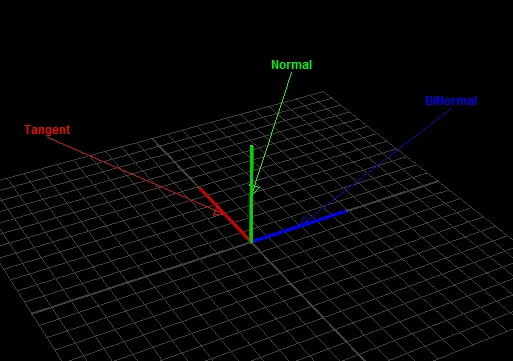
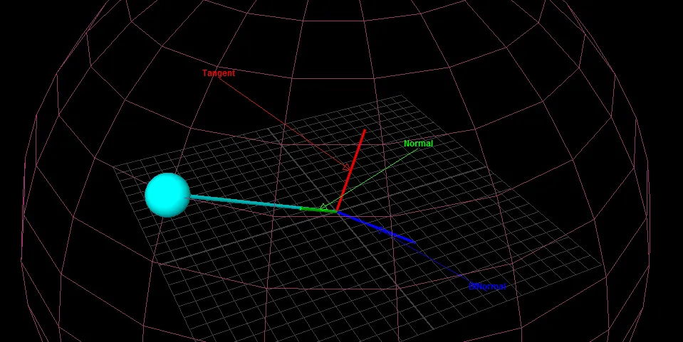
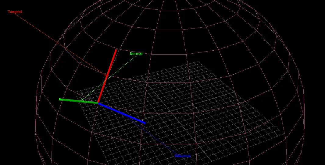
编辑 我以前不知道为什么没有这样做,但是现在我已经在几何着色器中输出了法线、切线和副切线,以查看它们的朝向。我使用了这个教程。
黄色是面法线,绿色是顶点法线。我不确定为什么顶点法线看起来有问题,它们不会影响任何其他光照,所以可能只是我的几何着色器中存在错误。
切线是红色的,副切线是蓝色的。它们似乎(很难说)是相互垂直的,这是正确的,但除此之外它们没有指向均匀的方向。这就是我之前显示出斑驳图案的原因。
我不知道该如何解决这个问题。
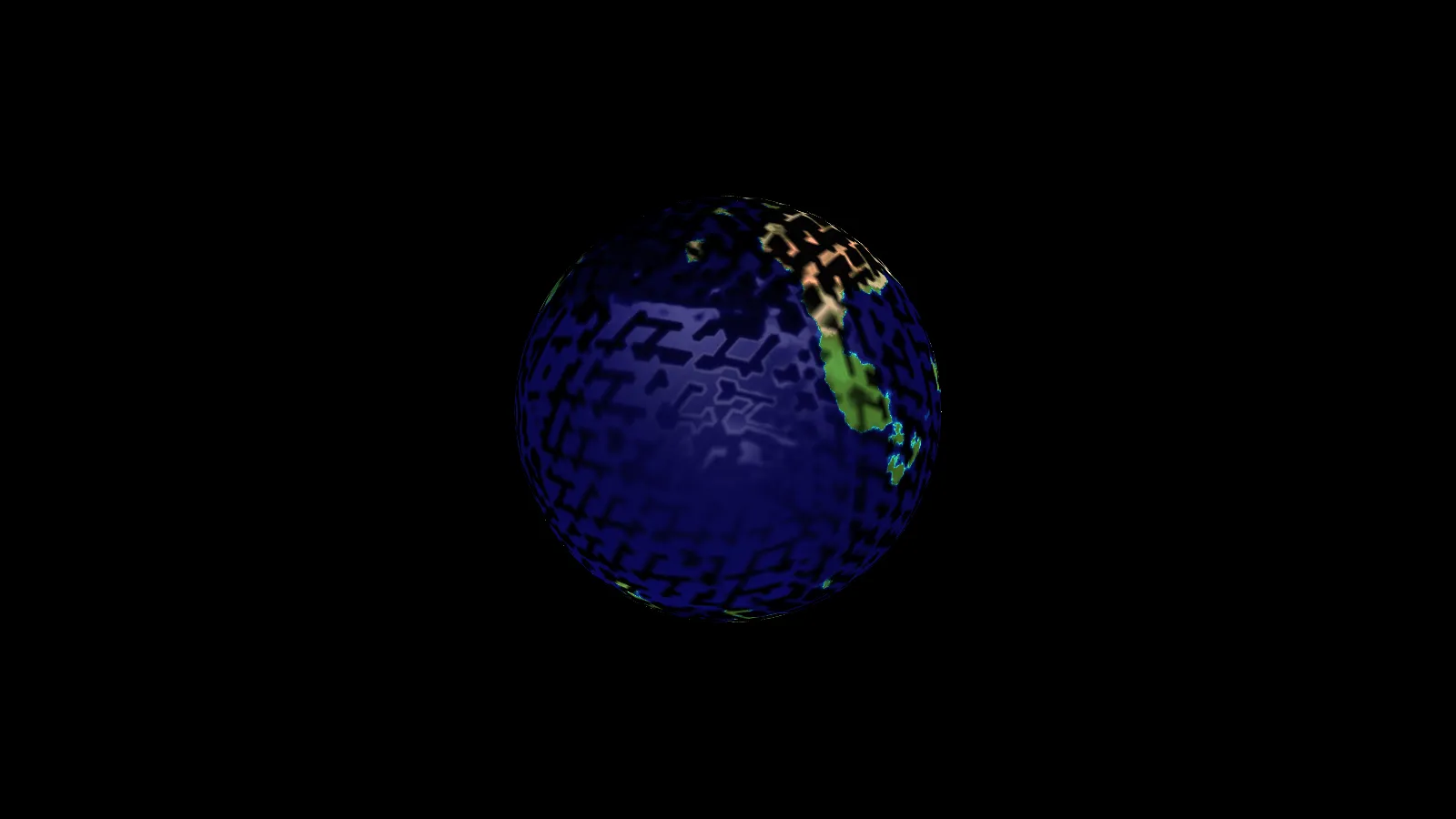
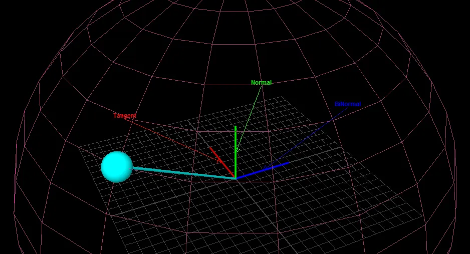
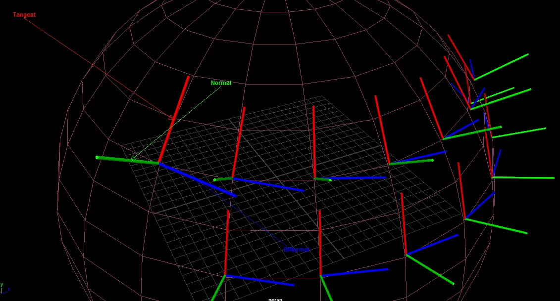
编辑 2 我已经找到了显示法线等内容的问题,现在已经解决了。
我添加了一些阴影以使结果更清晰,每种颜色代表不同的立方体面。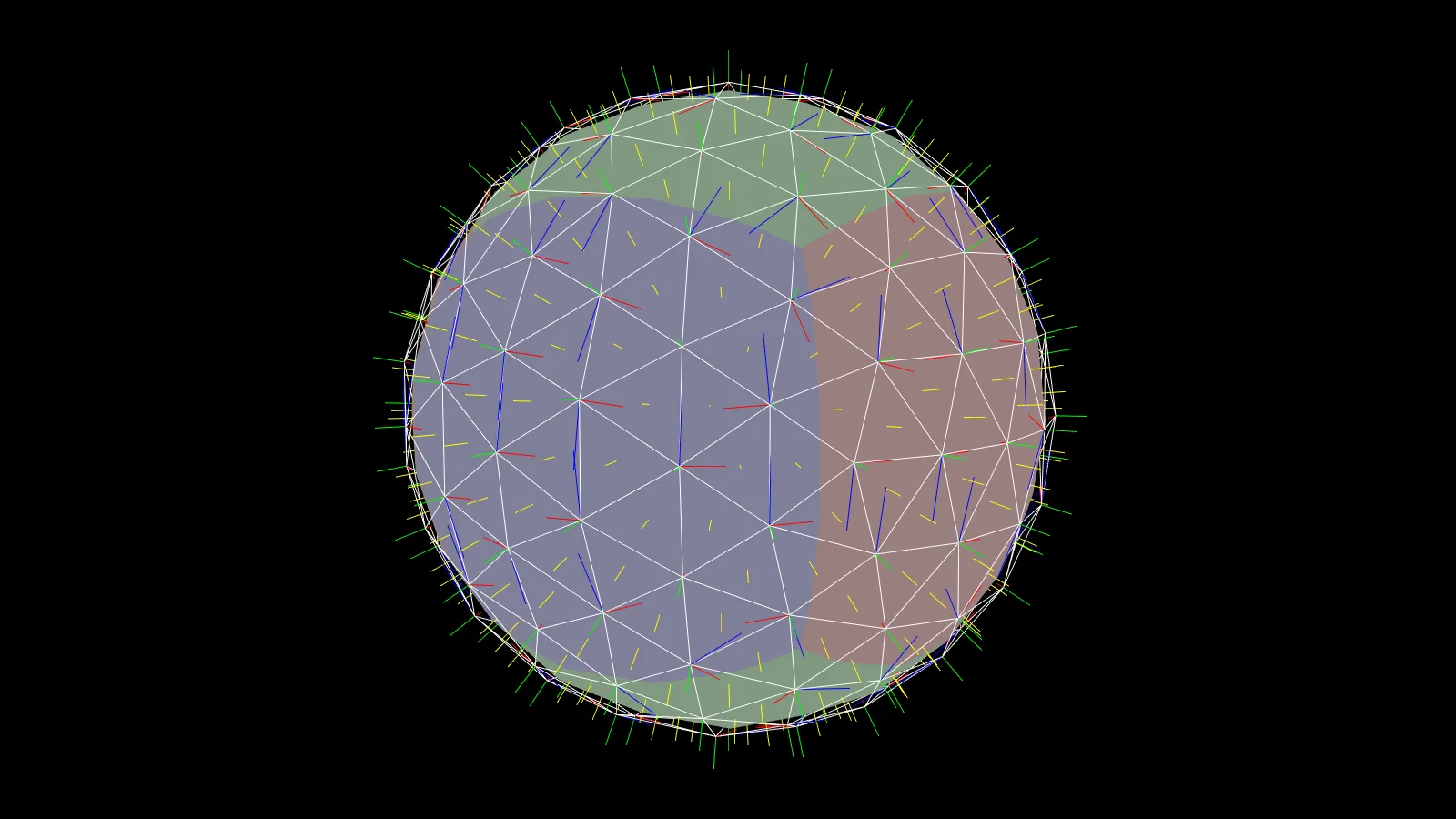
我改变的另一件事是查找我的法线贴图。我忘记将范围调整回-1到1(从0到1)。
normal = texture(mat.normal,textureLookup).rgb * 2.0 - 1.0;
这并没有解决我的问题。
令人困惑的是,当我尝试使用纹理中的法线时,我没有渲染出任何东西。深度缓冲区中什么也没有。我已经检查了多次,确认着色器可以访问纹理(这就是最初截图显示球体应用了纹理的原因)。
即使我的切线和副法线指向各个方向,我仍然期望能够展示一些东西,即使它是错误的。但连环境颜色都不显示。(即使我不改变我的 lightDir 和 viewdir,如果我只忽略顶点法线并查找纹理,我也会失去环境颜色)......
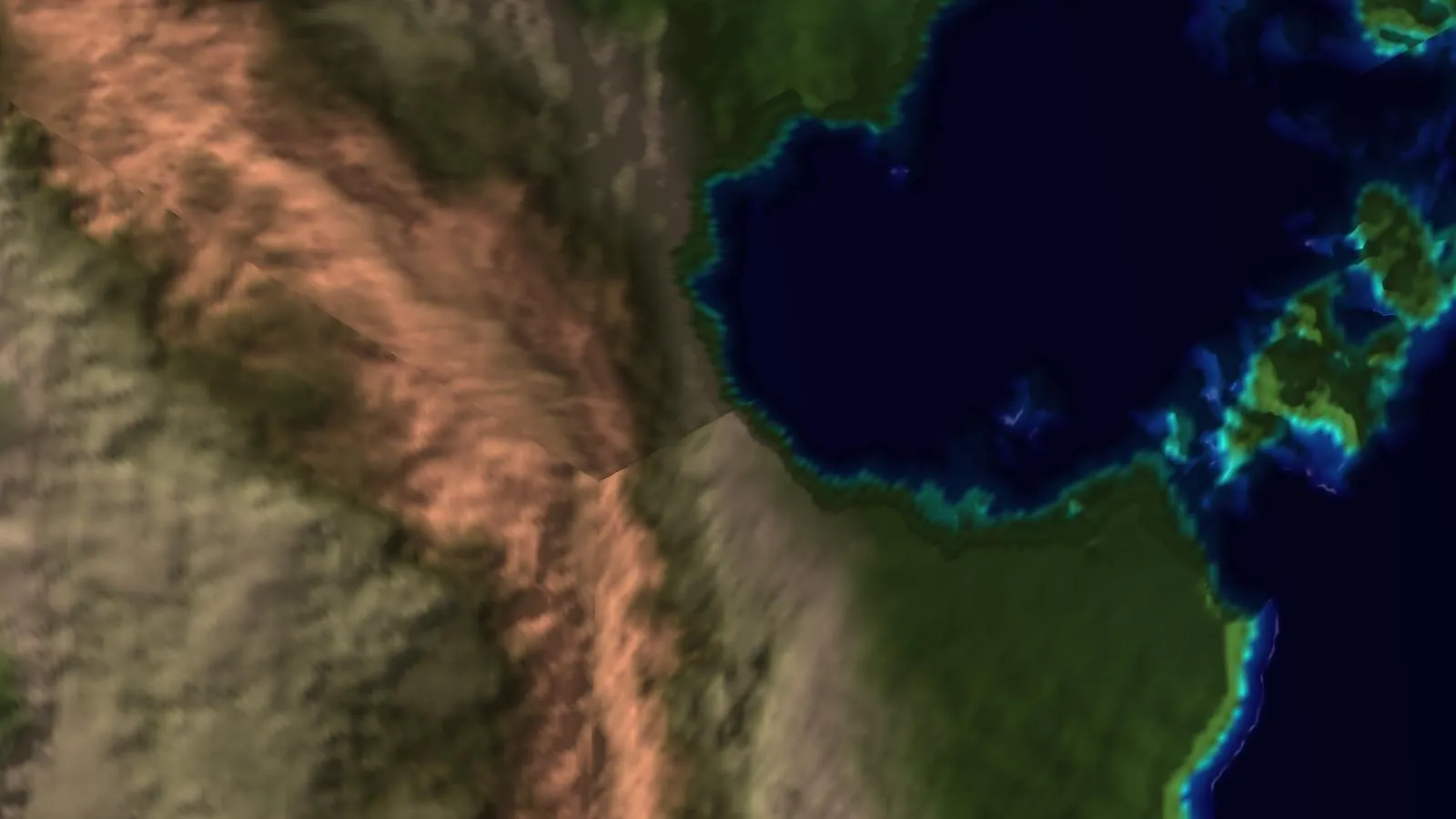
编辑3:最后一个问题
通常情况下,问题的一部分与您认为的错误无关。我的问题在于我正在使用另一个纹理覆盖我的法线贴图的绑定。
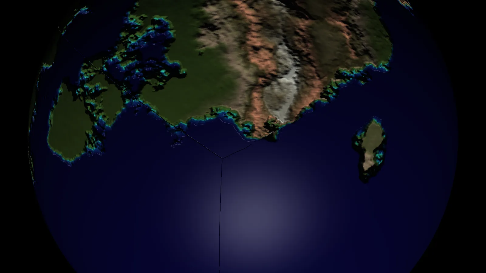
所以,现在这个问题解决了,我可以看到我的颜色展示了出来。带有美妙的凸凹映射效果。
然而,现在立方体贴图的接缝处出现了问题。我不确定这是由于切线计算还是由于我的法线贴图生成方式所致。我的法线贴图是从每个面的高度图独立生成的。我认为这可以解释一些接缝效果,我将修改它以在这些边缘采样相邻的面,并观察结果。
我仍然认为生成的切线也会对这些接缝产生不利影响。我的想法是它们在接缝处会指向相反的方向。
屏幕截图:
 编辑4:
在测试EDIT1以下时,我使用了一个非常低多边形网格来制作我的球体。因此我只有最少的子网格。
编辑4:
在测试EDIT1以下时,我使用了一个非常低多边形网格来制作我的球体。因此我只有最少的子网格。我想看看我的不太完美的法线贴图球在具有很多多边形的情况下如何表现。这立即揭示了这个问题:
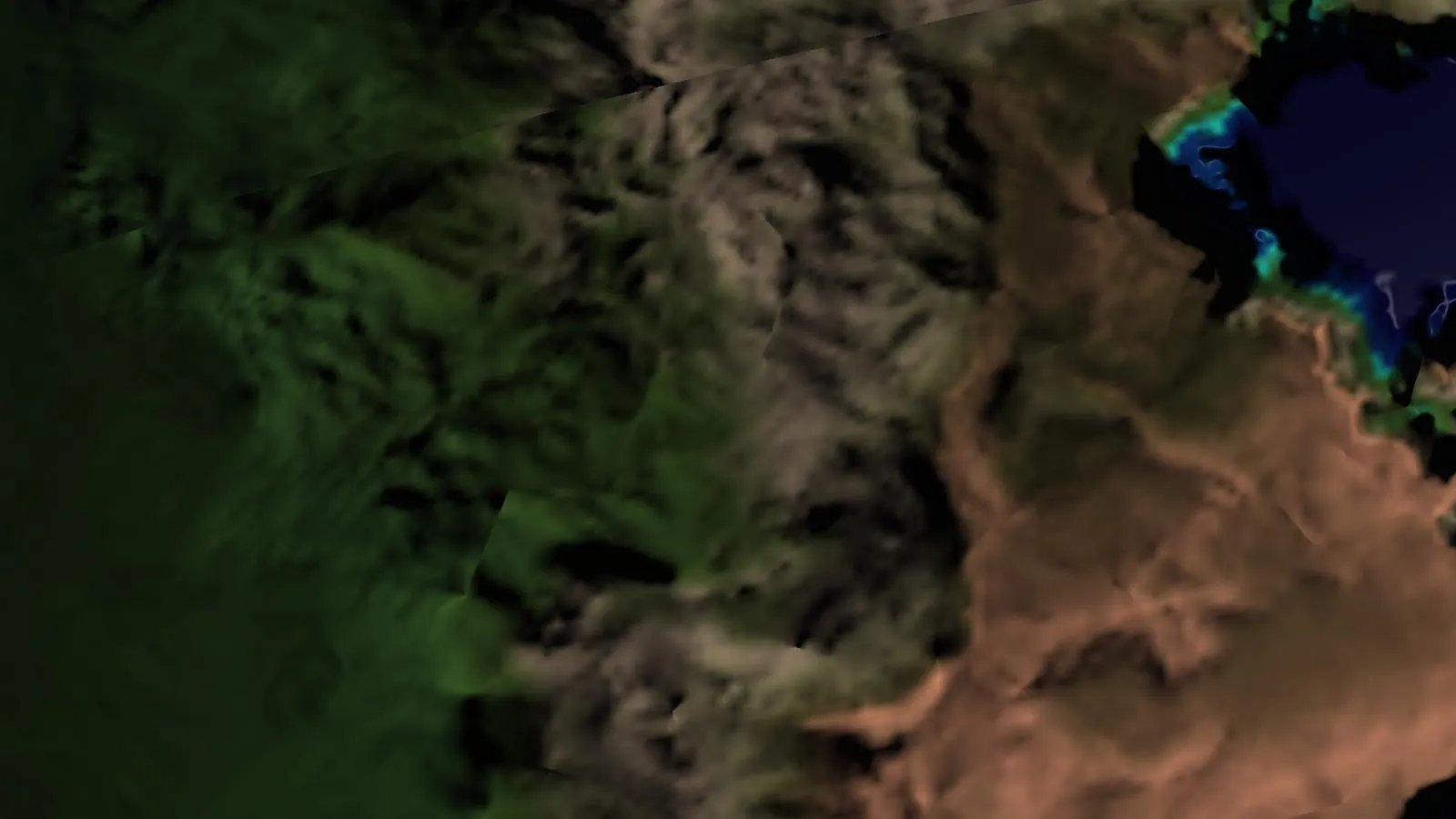
所以经过以上所有步骤后,我认为我又回到了最初的问题,即错误的切线。
仍然在寻求任何阅读此文的人的帮助。
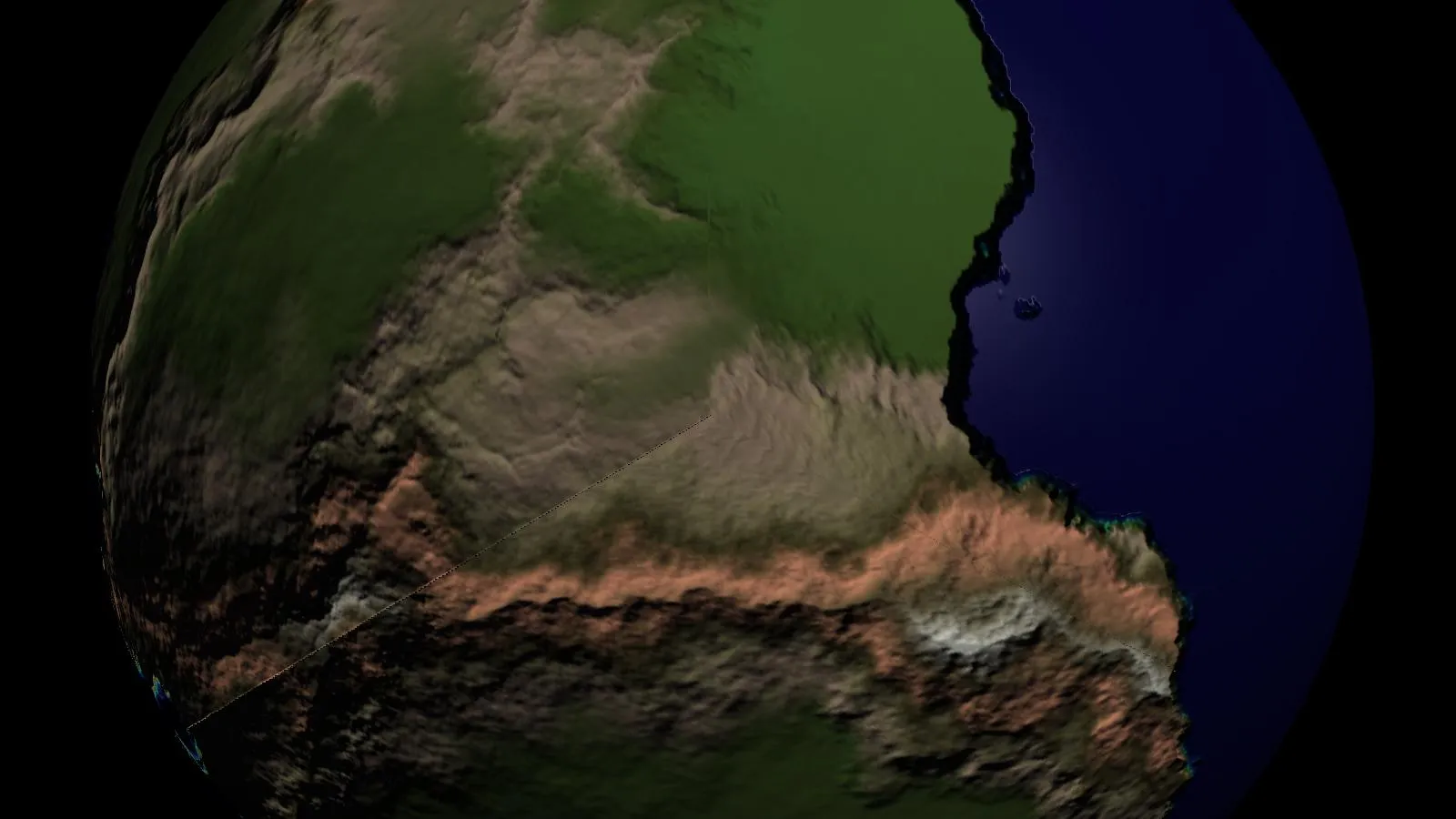
编辑4: 好吧,那很快。这个网站http://www.geeks3d.com/20130122/normal-mapping-without-precomputed-tangent-space-vectors/给了我另一种创建切线的方式。虽然代码似乎与我在CPU上所做的有些相似,但它没有产生EDIT 3中产生那些随机方向的切线所产生的边缘。
我现在非常接近了。我仍然有接缝,这种生成切线的其他方法似乎增加了它们的“接缝性”。
编辑 5 我现在尝试修改我的普通地图生成代码。之前的代码是这样的:
for(int i = 0; i < 6; ++i)
{
    float scale = 15.0;
    std::deque<glm::vec4> normalMap(textureSize*textureSize);
    for(int x = 0; x < textureSize; ++x)
    {
        for(int y = 0; y < textureSize; ++y)
        {
            // center point
            int i11 = utils::math::get_1d_array_index_from_2d(x,y,textureSize);
            float v11 = cubeFacesHeight[i][i11].r;

            // to the left
            int i01 = utils::math::get_1d_array_index_from_2d(std::max(x-1,0),y,textureSize);
            float v01 = cubeFacesHeight[i][i01].r;

            // to the right
            int i21 = utils::math::get_1d_array_index_from_2d(std::min(x+1,textureSize-1),y,textureSize);
            float v21 = cubeFacesHeight[i][i21].r;

            // to the top
            int i10 = utils::math::get_1d_array_index_from_2d(x,std::max(y-1,0),textureSize);
            float v10 = cubeFacesHeight[i][i10].r;

            // and now the bottom
            int i12 = utils::math::get_1d_array_index_from_2d(x,std::min(y+1,textureSize-1),textureSize);
            float v12 = cubeFacesHeight[i][i12].r;

            glm::vec3 S = glm::vec3(1, 0, scale * v21 - scale * v01);
            glm::vec3 T = glm::vec3(0, 1, scale * v12 - scale * v10);

            glm::vec3 N = (glm::vec3(-S.z,-T.z,1) / std::sqrt(S.z*S.z + T.z*T.z + 1));

            N.x = (N.x+1.0)/2.0;
            N.y = (N.y+1.0)/2.0;
            N.z = (N.z+1.0)/2.0;
            normalMap[utils::math::get_1d_array_index_from_2d(x,y,textureSize)] = glm::vec4(N.x,N.y,N.z,v11);
        }
    }
    for(int x = 0; x < textureSize; ++x)
    {
        for(int y = 0; y < textureSize; ++y)
        {
            cubeFacesHeight[i][utils::math::get_1d_array_index_from_2d(x,y,textureSize)] = normalMap[utils::math::get_1d_array_index_from_2d(x,y,textureSize)];
        }
    }
}
cubeFacesHeight 是一个包含 6 个 std::deque 的 glm::vec4 数组,代表我的立方体贴图的六个面。每个面的颜色都是灰度的,我没有使用浮点数是因为原因无关紧要。
现在我已经对其进行了修改,但警告:这很丑,也很长。
for(int i = 0; i < 6; ++i)
{
    // 0 is negative X
    // 1 is positive X
    // 2 is negative Y
    // 3 is positive Y
    // 4 is negative Z
    // 5 is positive Z

    // +X:  right -Z (left),    left +Z (right),    top -Y (right),     bottom +Y (right)
    // -X:  right +Z (left),    left -Z (right),    top -Y (left),      bottom +Y (left)
    // -Z:  right -X (left),    left +X (right),    top -Y (bottom),    bottom +Y (top)
    // +Z:  right +X (left),    left -X (right),    top -Y (top),       bottom +Y (bottom)
    // -Y:  right +X (top),     left -X (top),      top +Z (top),       bottom -Z (top)
    // +Y:  right +X (bottom),  left -X (bottom),   top -Z (bottom),    bottom +Z (bottom)

    //+Z is towards, -Z is distance
    const int NEGATIVE_X = 0;
    const int NEGATIVE_Y = 2;
    const int NEGATIVE_Z = 4;
    const int POSITIVE_X = 1;
    const int POSITIVE_Y = 3;
    const int POSITIVE_Z = 5;

    float scale = 15.0;
    std::deque<glm::vec4> normalMap(textureSize*textureSize);
    for(int x = 0; x < textureSize; ++x)
    {
        for(int y = 0; y < textureSize; ++y)
        {
            // center point
            int i11 = utils::math::get_1d_array_index_from_2d(x,y,textureSize);
            float v11 = cubeFacesHeight[i][i11].r;

            // to the left
            int i01 = utils::math::get_1d_array_index_from_2d(std::max(x-1,0),y,textureSize);
            float v01 = cubeFacesHeight[i][i01].r;
            if(x-1 < 0)
            {
                if(i == NEGATIVE_X)
                {
                    i01 = utils::math::get_1d_array_index_from_2d(textureSize-1,y,textureSize);
                    v01 = cubeFacesHeight[NEGATIVE_Z][i01].r;
                }
                else if(i == POSITIVE_X)
                {
                    i01 = utils::math::get_1d_array_index_from_2d(textureSize-1,y,textureSize);
                    v01 = cubeFacesHeight[POSITIVE_Z][i01].r;
                }
                else if(i == NEGATIVE_Z)
                {
                    i01 = utils::math::get_1d_array_index_from_2d(textureSize-1,y,textureSize);
                    v01 = cubeFacesHeight[POSITIVE_X][i01].r;
                }
                else if(i == POSITIVE_Z)
                {
                    i01 = utils::math::get_1d_array_index_from_2d(textureSize-1,y,textureSize);
                    v01 = cubeFacesHeight[NEGATIVE_X][i01].r;
                }
                else if(i == NEGATIVE_Y)
                {
                    i01 = utils::math::get_1d_array_index_from_2d(y,0,textureSize);
                    v01 = cubeFacesHeight[NEGATIVE_X][i01].r;
                }
                else if(i == POSITIVE_Y)
                {
                    i01 = utils::math::get_1d_array_index_from_2d(y,textureSize-1,textureSize);
                    v01 = cubeFacesHeight[NEGATIVE_X][i01].r;
                }
            }

            // to the right
            int i21 = utils::math::get_1d_array_index_from_2d(std::min(x+1,textureSize-1),y,textureSize);
            float v21 = cubeFacesHeight[i][i21].r;
            if(x+1 > textureSize-1)
            {
                if(i == NEGATIVE_X)
                {
                    i01 = utils::math::get_1d_array_index_from_2d(0,y,textureSize);
                    v01 = cubeFacesHeight[POSITIVE_Z][i01].r;
                }
                else if(i == POSITIVE_X)
                {
                    i01 = utils::math::get_1d_array_index_from_2d(0,y,textureSize);
                    v01 = cubeFacesHeight[NEGATIVE_Z][i01].r;
                }
                else if(i == NEGATIVE_Z)
                {
                    i01 = utils::math::get_1d_array_index_from_2d(0,y,textureSize);
                    v01 = cubeFacesHeight[NEGATIVE_X][i01].r;
                }
                else if(i == POSITIVE_Z)
                {
                    i01 = utils::math::get_1d_array_index_from_2d(0,y,textureSize);
                    v01 = cubeFacesHeight[POSITIVE_X][i01].r;
                }
                else if(i == NEGATIVE_Y)
                {
                    i01 = utils::math::get_1d_array_index_from_2d(y,0,textureSize);
                    v01 = cubeFacesHeight[POSITIVE_X][i01].r;
                }
                else if(i == POSITIVE_Y)
                {
                    i01 = utils::math::get_1d_array_index_from_2d(y,textureSize-1,textureSize);
                    v01 = cubeFacesHeight[POSITIVE_X][i01].r;
                }
            }

            // to the top
            int i10 = utils::math::get_1d_array_index_from_2d(x,std::max(y-1,0),textureSize);
            float v10 = cubeFacesHeight[i][i10].r;
            if(y-1 < 0)
            {
                if(i == NEGATIVE_X)
                {
                    i01 = utils::math::get_1d_array_index_from_2d(0,x,textureSize);
                    v01 = cubeFacesHeight[NEGATIVE_Y][i01].r;
                }
                else if(i == POSITIVE_X)
                {
                    i01 = utils::math::get_1d_array_index_from_2d(textureSize-1,x,textureSize);
                    v01 = cubeFacesHeight[NEGATIVE_Y][i01].r;
                }
                else if(i == NEGATIVE_Z)
                {
                    i01 = utils::math::get_1d_array_index_from_2d(x,textureSize-1,textureSize);
                    v01 = cubeFacesHeight[NEGATIVE_Y][i01].r;
                }
                else if(i == POSITIVE_Z)
                {
                    i01 = utils::math::get_1d_array_index_from_2d(x,0,textureSize);
                    v01 = cubeFacesHeight[NEGATIVE_Y][i01].r;
                }
                else if(i == NEGATIVE_Y)
                {
                    i01 = utils::math::get_1d_array_index_from_2d(x,0,textureSize);
                    v01 = cubeFacesHeight[POSITIVE_Z][i01].r;
                }
                else if(i == POSITIVE_Y)
                {
                    i01 = utils::math::get_1d_array_index_from_2d(x,textureSize-1,textureSize);
                    v01 = cubeFacesHeight[NEGATIVE_Z][i01].r;
                }
            }

            // and now the bottom
            int i12 = utils::math::get_1d_array_index_from_2d(x,std::min(y+1,textureSize-1),textureSize);
            float v12 = cubeFacesHeight[i][i12].r;
            if(y+1 > textureSize-1)
            {
                if(i == NEGATIVE_X)
                {
                    i01 = utils::math::get_1d_array_index_from_2d(0,x,textureSize);
                    v01 = cubeFacesHeight[POSITIVE_Y][i01].r;
                }
                else if(i == POSITIVE_X)
                {
                    i01 = utils::math::get_1d_array_index_from_2d(textureSize-1,x,textureSize);
                    v01 = cubeFacesHeight[POSITIVE_Y][i01].r;
                }
                else if(i == NEGATIVE_Z)
                {
                    i01 = utils::math::get_1d_array_index_from_2d(x,0,textureSize);
                    v01 = cubeFacesHeight[POSITIVE_Y][i01].r;
                }
                else if(i == POSITIVE_Z)
                {
                    i01 = utils::math::get_1d_array_index_from_2d(x,textureSize-1,textureSize);
                    v01 = cubeFacesHeight[POSITIVE_Y][i01].r;
                }
                else if(i == NEGATIVE_Y)
                {
                    i01 = utils::math::get_1d_array_index_from_2d(x,0,textureSize);
                    v01 = cubeFacesHeight[NEGATIVE_Z][i01].r;
                }
                else if(i == POSITIVE_Y)
                {
                    i01 = utils::math::get_1d_array_index_from_2d(x,textureSize-1,textureSize);
                    v01 = cubeFacesHeight[POSITIVE_Z][i01].r;
                }
            }

            glm::vec3 S = glm::vec3(1, 0, scale * v21 - scale * v01);
            glm::vec3 T = glm::vec3(0, 1, scale * v12 - scale * v10);

            glm::vec3 N = (glm::vec3(-S.z,-T.z,1) / std::sqrt(S.z*S.z + T.z*T.z + 1));

            N.x = (N.x+1.0)/2.0;
            N.y = (N.y+1.0)/2.0;
            N.z = (N.z+1.0)/2.0;

            normalMap[utils::math::get_1d_array_index_from_2d(x,y,textureSize)] = glm::vec4(N.x,N.y,N.z,v11);
        }
    }
    for(int x = 0; x < textureSize; ++x)
    {
        for(int y = 0; y < textureSize; ++y)
        {
            cubeFacesHeight[i][utils::math::get_1d_array_index_from_2d(x,y,textureSize)] = normalMap[utils::math::get_1d_array_index_from_2d(x,y,textureSize)];
        }
    }
}
现在我正在将采样高度的过程“渗透”到相邻的立方体面上,同时生成法线贴图。这实际上增加了接缝的出现。
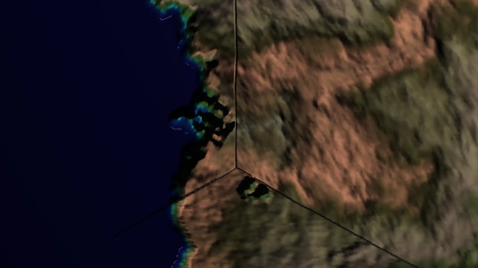
所以,我相当确定当“渗透”到下一个面时已经正确地匹配了我的立方体面。这让我回到了切线不正确的问题上。
即使我完全混淆了立方体面,也不会产生斜角效果,而是完全不连贯的东西。例如,即使在完全平坦的部分上,即将法线图生成渗入到下一个面中也不会产生任何影响,我仍然看到一个巨大的斜角。
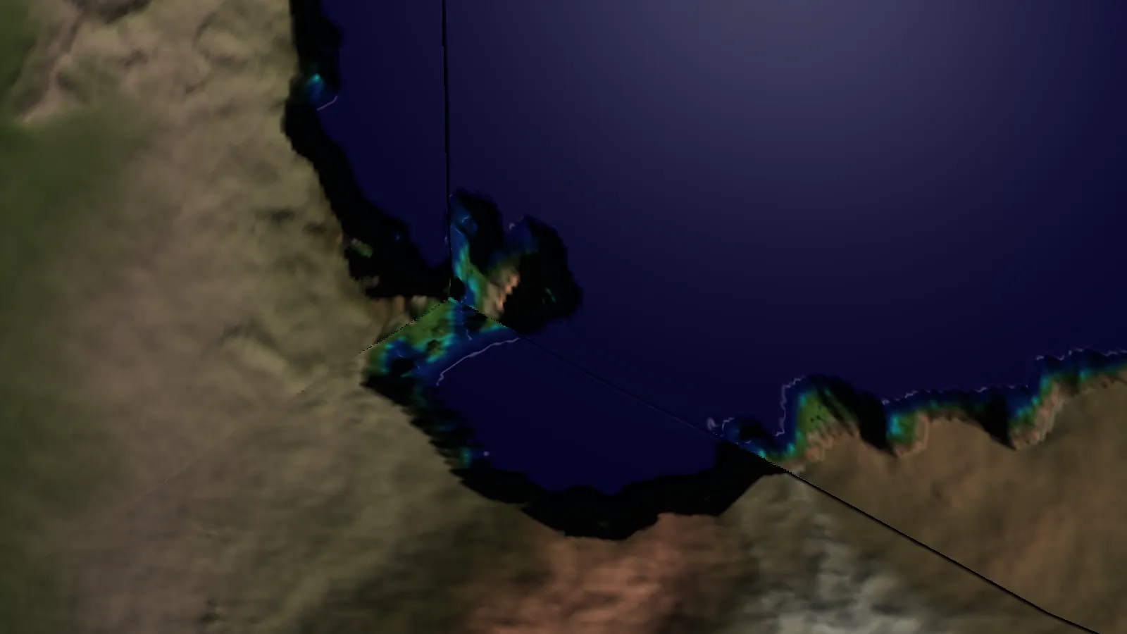 我在这里可以看到两个不同的面“指向”相反的方向。这是通过我的片段切线生成得出的。
所以我又回到了我的切线存在问题。