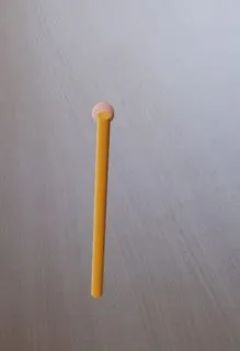
我有一些水平面,在那里我设置了我想要绘制的线的起点。
现在我想要从起点画一条垂直线到相机的中心,也就是ArFragment。 目前我的做法如下:
当我能够将智能手机垂直握住时,这个功能按预期运行。 当我旋转相机时,由于创建的锚点不再位于屏幕中央,该线不再绘制到中央。 是否有官方或更好的方法可以使竖线如预期般工作,无论我如何握住智能手机? 更新:现在我已经通过计算交点来创建了一条线。
唯一的问题是该线必须恰好位于智能手机的中心位置(右侧、左侧)。
然后我们离开该线段一些距离,看着我们想要终点的位置。
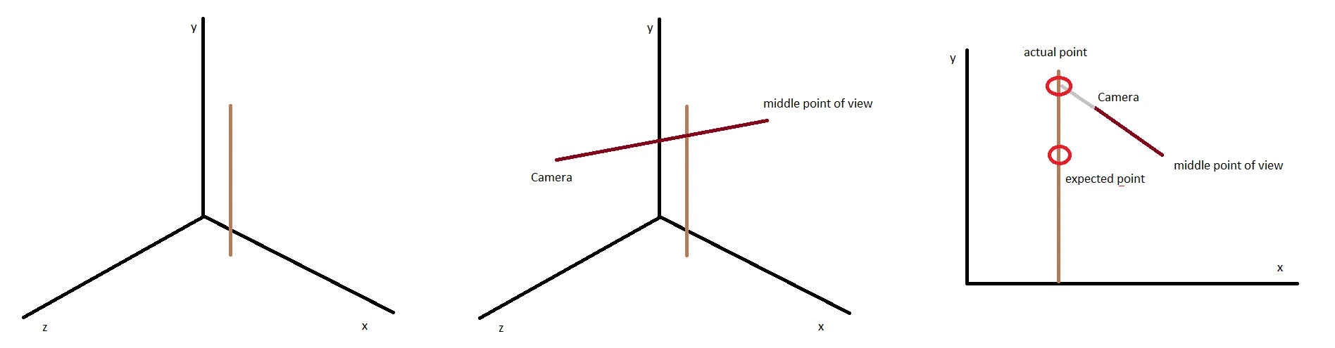
现在我将问题看作是2D的,并想象我的相机起点和终点与线段在同一个xy-room中,计算出线段的终点。
问题是,我的相机视图的起点和终点具有不同的z值,与我画的线段不同。
需要找到相机视图矢量上与线段在同一个xy-room中(线段的z = 点的z)的点(及其y值)。
有人有想法吗?
现在我想要从起点画一条垂直线到相机的中心,也就是ArFragment。 目前我的做法如下:
// create an anchor 1 meter away of current camera position and rotation
Anchor anchor = arFragment.getArSceneView().getSession().createAnchor(
            arFragment.getArSceneView().getArFrame().getCamera().getPose()
                    .compose(Pose.makeTranslation(0, 0, -1f))
                    .extractTranslation());

// create AnchorNode with position data of Anchor
AnchorNode anchorNode = new AnchorNode(anchor);
// remove anchor to be free change position of AnchorNode
anchorNode.setAnchor(null);
// get local position of new anchor node
Vector3 newLocPos = anchorNode.getLocalPosition();

// get the local position of start node
Vector3 fromVector = fromNode.getLocalPosition();

// since we want to make vertical line, set x and z of new AnchorNode to same as start
newLocPos.x = fromVector.x;
newLocPos.z = fromVector.z;
// set updated position data to new AnchorNode
anchorNode.setLocalPosition(newLocPos);
// set scene as parent to have node in UI
anchorNode.setParent(arFragment.getArSceneView().getScene());

// draw line between Nodes
....
当我能够将智能手机垂直握住时,这个功能按预期运行。 当我旋转相机时,由于创建的锚点不再位于屏幕中央,该线不再绘制到中央。 是否有官方或更好的方法可以使竖线如预期般工作,无论我如何握住智能手机? 更新:现在我已经通过计算交点来创建了一条线。
private static MyPoint calculateIntersectionPoint(MyPoint A, MyPoint B, MyPoint C, MyPoint D) {
    // Line AB represented as a1x + b1y = c1
    double a1 = B.y - A.y;
    double b1 = A.x - B.x;
    double c1 = a1 * (A.x) + b1 * (A.y);

    // Line CD represented as a2x + b2y = c2
    double a2 = D.y - C.y;
    double b2 = C.x - D.x;
    double c2 = a2 * (C.x) + b2 * (C.y);

    double determinant = a1 * b2 - a2 * b1;

    if (determinant == 0) {
        // The lines are parallel. This is simplified
        // by returning a pair of FLT_MAX
        return new MyPoint(Double.MAX_VALUE, Double.MAX_VALUE);
    } else {
        double x = (b2 * c1 - b1 * c2) / determinant;
        double y = (a1 * c2 - a2 * c1) / determinant;
        return new MyPoint(x, y);
    }
}


MyPoint interceptionPoint = calculateIntersectionPoint(
    new MyPoint(line1From.getWorldPosition().x, line1From.getWorldPosition().y),
    new MyPoint(line1To.getWorldPosition().x, line1To.getWorldPosition().y),
    new MyPoint(line2From.getWorldPosition().x, line2From.getWorldPosition().y),
    new MyPoint(line2To.getWorldPosition().x, line2To.getWorldPosition().y));

// get local position of new anchor node
Vector3 newLocPos = anchorNode.getWorldPosition();
// since we want to make vertical line, set x and z of new AnchorNode to same as start
newLocPos.y = (float) interceptionPoint.y;
newLocPos.x = fromVector.x;
newLocPos.z = fromVector.z;

// set updated position data to new AnchorNode
anchorNode.setWorldPosition(newLocPos);
唯一的问题是该线必须恰好位于智能手机的中心位置(右侧、左侧)。

然后我们离开该线段一些距离,看着我们想要终点的位置。
现在我将问题看作是2D的,并想象我的相机起点和终点与线段在同一个xy-room中,计算出线段的终点。
问题是,我的相机视图的起点和终点具有不同的z值,与我画的线段不同。
需要找到相机视图矢量上与线段在同一个xy-room中(线段的z = 点的z)的点(及其y值)。
有人有想法吗?
Node(com.google.ar.sceneform.AnchorNode@a8c1dff)。但是线条没有显示出来。有什么提示吗? - exper_1