这个CG程序有什么问题吗?

7

我正在使用Ogre3D作为图形引擎。

我手动创建了一个网格,它工作正常,UV坐标是正确的,并且设置为表示网格坐标(对于这个示例,网格为10 x 10)。

我在顶点程序中什么也不做,并且有一个非常简单的片段程序。我已经包含了两个程序以及材料文件来解释。

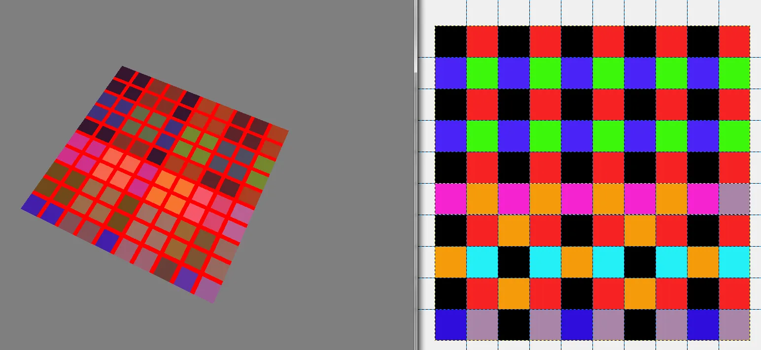
我的问题是,即使将过滤设置为“无”,颜色似乎也不能与我的原始图像相同(这只是一个测试图像,因为我在手动在ogre中创建纹理时遇到了问题)。事实证明,问题不在于我在ogre中的代码,而更可能是与材质文件或片段/顶点程序有关的问题。

我还在左侧包含了输出的屏幕截图和右侧的原始图像。片段着色器还绘制了一个简单的网格,以便确保UV坐标被正确传递。看起来它们是正确的。

enter image description here

如果您有任何见解,将不胜感激,因为我真的不确定我做错了什么。

材料文件:

// CG Vertex shader definition
vertex_program PlainTexture_VS cg            
{
    // Look in this source file for shader code
    source GameObjStandard.cg
    // Use this function for the vertex shader            
    entry_point main_plain_texture_vp    
    // Compile the shader to vs_1_1 format    
    profiles arbvp1       

    // This block saves us from manually setting parameters in code
    default_params                    
    {
        // Ogre will put the worldviewproj into our 'worldViewProj' parameter for us.
        param_named_auto worldViewProj worldviewproj_matrix        
        // Note that 'worldViewProj' is a parameter in the cg code.
    }
}

// CG Pixel shader definition
fragment_program PlainTexture_PS cg            
{
    // Look in this source file for shader code
    source GameObjStandard.cg        
    // Use this function for the pixel shader    
    entry_point main_plain_texture_fp    
    // Compile to ps_1_1 format    
    profiles arbfp1             
}

material PlainTexture
{
    // Material has one technique
    technique                  
    {
        // This technique has one pass
        pass                   
        {
            // Make this pass use the vertex shader defined above
            vertex_program_ref PlainTexture_VS    
            {
            }
            // Make this pass use the pixel shader defined above
            fragment_program_ref PlainTexture_PS    
            {
            }
            texture_unit 0
            {
                filtering none
                // This pass will use this 2D texture as its input
                texture test.png 2d        
            }
            texture_unit 1
            {
                texture textureatlas.png 2d
                tex_address_mode clamp
                filtering none
            }
        }
    }
}

CG文件:

void main_plain_texture_vp(
    // Vertex Inputs
    float4 position        : POSITION,    // Vertex position in model space
    float2 texCoord0    : TEXCOORD0,    // Texture UV set 0

    // Outputs
    out float4 oPosition    : POSITION,    // Transformed vertex position
    out float2 uv0        : TEXCOORD0,    // UV0

    // Model Level Inputs
    uniform float4x4 worldViewProj)
{
    // Calculate output position
    oPosition = mul(worldViewProj, position);

    // Simply copy the input vertex UV to the output
    uv0 = texCoord0;
}

void main_plain_texture_fp(
    // Pixel Inputs
    float2 uv0        : TEXCOORD0,    // UV interpolated for current pixel

    // Outputs
    out float4 color    : COLOR,    // Output color we want to write

    // Model Level Inputs
    uniform sampler2D Tex0: TEXUNIT0,

uniform sampler2D Tex1: TEXUNIT1)        // Texture we're going to use
{

//get the index position by truncating the uv coordinates
float2 flooredIndexes = floor(uv0);

if((uv0.x > 0.9 && uv0.x < 1.1)
|| (uv0.x > 1.9 && uv0.x < 2.1)
|| (uv0.x > 2.9 && uv0.x < 3.1)
|| (uv0.x > 3.9 && uv0.x < 4.1)
|| (uv0.x > 4.9 && uv0.x < 5.1)
|| (uv0.x > 5.9 && uv0.x < 6.1)
|| (uv0.x > 6.9 && uv0.x < 7.1)
|| (uv0.x > 7.9 && uv0.x < 8.1)
|| (uv0.x > 8.9 && uv0.x < 9.1)) {
   float4 color1 = {1.0,0,0,0};
   color = color1;
} else if((uv0.y > 0.9 && uv0.y < 1.1)
|| (uv0.y > 1.9 && uv0.y < 2.1)
|| (uv0.y > 2.9 && uv0.y < 3.1)
|| (uv0.y > 3.9 && uv0.y < 4.1)
|| (uv0.y > 4.9 && uv0.y < 5.1)
|| (uv0.y > 5.9 && uv0.y < 6.1)
|| (uv0.y > 6.9 && uv0.y < 7.1)
|| (uv0.y > 7.9 && uv0.y < 8.1)
|| (uv0.y > 8.9 && uv0.y < 9.1)) {
   float4 color1 = {1.0,0,0,0};
   color = color1;
} else {
   //get the colour of the index texture Tex0 at this floored coordinate
   float4 indexColour = tex2D(Tex0, (1.0/10)*flooredIndexes);
   color = indexColour;
}
}

谢谢您的编辑,我不确定如何插入图片 :) - Jon Taylor
不确定是否有帮助,它没有解决问题。我将1/10乘以的原因是因为uv0中的索引目前在u和v方向上都从0到10运行。我对这个值进行了下取整,因为它在片段程序中进行了插值,所以我得到像5.6这样的值,如果我对这个值进行下取整,我就得到了5,这个值除以瓷砖宽度(10)给我所需的uv坐标,0.5。 - Jon Taylor
我现在已经解决了这个问题。今晚稍后我会发布一篇回答,详细说明问题和解决方案,如果有人读到这个并感兴趣的话。 - Jon Taylor
当然,请这么做!是的,我知道我来晚了 :) - TheSHEEEP
@TheSHEEEP 抱歉最近很忙,想在这里发布一个适当的答案。我有一个解决方案,如果今晚没有时间,那么这个周末会发布它。 - Jon Taylor
显示剩余2条评论
1个回答

7

好的,我已经有一段时间没有找到解决问题的方法了。不幸的是,我一直没有上网,所以希望这篇文章能够帮助到那些遇到类似问题的人。

在创建任何纹理时,你应该始终使用texels大小为2^n * 2^m,其中mn是纹理的宽度和高度。这是我的第一个错误,尽管当时我没有意识到它。

我之所以没有发现这一点是因为我的主要纹理图集基于这个原则,是一个1024 x 1024的纹理。然而,我没有考虑到我作为纹理索引所创建的纹理的大小。由于我的地图是10 x 10,我正在创建一个10 x 10的纹理用作索引,这被我推测是被拉伸了,最终成为16 x 16或8 x 8,同时混合着texels。

给我线索的第一件事是当我在photoshop中缩放画布时,发现它创建的混合颜色与我在ogre3d输出中得到的颜色相同。

总之,我们继续说吧。

一旦我弄清楚了这个问题,我就可以在Ogre中创建纹理,并按以下方式传递它:

//Create index material
Ogre::TexturePtr indexTexture = Ogre::TextureManager::getSingleton().createManual("indexTexture","General",Ogre::TextureType::TEX_TYPE_2D, 16, 16, 0, Ogre::PixelFormat::PF_BYTE_BGRA, Ogre::TU_DEFAULT);

Ogre::HardwarePixelBufferSharedPtr pixelBuffer = indexTexture->getBuffer();
pixelBuffer->lock(Ogre::HardwareBuffer::HBL_NORMAL);

const Ogre::PixelBox& pixelBox = pixelBuffer->getCurrentLock();
Ogre::uint8* pDest = static_cast<Ogre::uint8*>(pixelBox.data);

Ogre::uint8 counter = 0;
for (size_t j = 0; j < 16; j++) {
for(size_t i = 0; i < 16; i++)
{       
        if(i==8 || i==7) {
    *pDest++ = 3;   // B
    *pDest++ = 0;   // G
    *pDest++ = 0;   // R
    *pDest++ = 0;   // A
    } else {
    *pDest++ = 1;   // B 
    *pDest++ = 0;   // G
    *pDest++ = 0;   // R
    *pDest++ = 0;   // A
    }
    counter++;
}
}

pixelBuffer->unlock();

现在我有一个纹理可以用作索引,并添加了一些测试值,这些值最终将在运行时通过单击瓷砖来填充。

现在要传递这个纹理,我必须将其传递到正确的技术中并传递我的材质,操作如下:

Ogre::MaterialPtr material = Ogre::MaterialPtr(Ogre::MaterialManager::getSingleton().getByName("PlainTexture"));
float mapSize = 16;
float tas = 2;
material->getTechnique(0)->getPass(0)->getFragmentProgramParameters()->setNamedConstant("mapSize",mapSize);
material->getTechnique(0)->getPass(0)->getFragmentProgramParameters()->setNamedConstant("tas",tas);
material->getTechnique(0)->getPass(0)->getTextureUnitState(0)->setTextureName("indexTexture");    

这也传递了两个值,mapSize表示地图本身在瓦片上的大小(假设它是正方形),tas表示纹理集大小(沿着纹理集宽度的不同纹理瓷砖数量)。
为了让我的材料理解我刚才传递的内容,我需要稍微修改一下我的材料文件,如下所示:
// CG Pixel shader definition
fragment_program PlainTexture_PS cg            
{
    source GameObjStandard.cg    
    entry_point main_plain_texture_fp 
    profiles arbfp1 
default_params
{
    param_named tas float
    param_named 
}            
}

我的密码稍微重新定义了一下

pass                   
{
                    // Make this pass use the vertex shader defined above
    vertex_program_ref PlainTexture_VS    
    {
    }
                    // Make this pass use the pixel shader defined above
    fragment_program_ref PlainTexture_PS    
    {
    }
    texture_unit 0
    {
        filtering none        
    }
texture_unit 1
{
    texture textureatlas.png 2d
    tex_address_mode clamp
    filtering anisotropic
}
}

然后,我重新编写了cg纹理片段程序,考虑到我所做的更改。

void main_plain_texture_fp(
    float2 uv0 : TEXCOORD0,    // UV interpolated for current pixel
    out float4 color    : COLOR,    // Output color we want to write
uniform float tas,
uniform float mapSize,

    // Model Level Inputs
    uniform sampler2D Tex0: TEXUNIT0,
uniform sampler2D Tex1: TEXUNIT1)
{
//get the index position by truncating the uv coordinates
float2 flooredIndexes = floor(uv0);

//get the colour of the index texture Tex0 at this floored coordinate
float4 indexColour = tex2D(Tex0, ((1.0/mapSize) * flooredIndexes)+(0.5/mapSize));

//calculate the uv offset required for texture atlas range = 0 - 255
float indexValue = (255 * indexColour.b) + (255 * indexColour.g) + (255 * indexColour.r);

//float indexValue = (tas * tas) - indexValue0;

if(indexValue < tas*tas) {
    float row = floor(indexValue/tas);
    float col = frac(indexValue/tas) * tas;

    float uvFraction = 1.0/tas;

    float uBase = col * uvFraction;
    float vBase =  1 - ((tas - row) * uvFraction);

    float uOffset = frac(uv0.x)/tas;
    float vOffset = (frac(uv0.y))/tas;

    float uNew = uBase + uOffset;
    float vNew = vBase + vOffset;

    float2 uvNew = {uNew, vNew};

    if(frac(uv0.x) > 0.99 || frac(uv0.x) < 0.01) {
    float4 color1 = {1,1,1,0};
    color = (0.2*color1) + (0.8*tex2D(Tex1,uvNew));
    } else if(frac(uv0.y) > 0.99 || frac(uv0.y) < 0.01) {
    float4 color1 = {1,1,1,0};
    color = (0.2*color1) + (0.8*tex2D(Tex1,uvNew));
    } else {
    color = tex2D(Tex1,uvNew);
    }


} else {
    float4 color2 = {0.0,0,0,0};
    color = color2;
}
}

这个功能可以计算从纹理图集中所需的正确像素,同时通过将80%的像素颜色和20%的白色混合在一起,在顶部覆盖一个淡淡的网格。
如果纹理图集中没有索引纹理指定的颜色索引,则只输出黑色(这主要是为了方便识别)。
下面是使用2 x 2纹理图集输出的示例。

@TheSHEEEP 希望这能帮到你或者引起你的兴趣。 - Jon Taylor
@TheSHEEEP 没问题,如果你在想,我忘了提到底部呈现的图像实际上并不完全符合上面的代码。上面的代码会在上方放置一个白色半透明网格,图像不考虑网格下面的纹理,只会将其涂成黑色。 - Jon Taylor

网页内容由stack overflow 提供, 点击上面的
可以查看英文原文,
原文链接