旋转立方体以成为等轴测体

4
我正在跟随这个旋转立方体教程,并尝试将立方体旋转到等角透视图(45度,30度)。
问题是,我认为,rotateY和rotateX函数会改变原始值,使得立方体中间的两个红点(在视觉上)不重叠。(如果有意义的话)
我该如何同时围绕X轴和Y轴旋转立方体,使得这些函数互不影响?

const canvas = document.getElementById('stage');
    canvas.width = canvas.parentElement.clientWidth
    canvas.height = canvas.parentElement.clientHeight
    const context = canvas.getContext('2d');
    context.translate(200,200)

    var node0 = [-100, -100, -100];
    var node1 = [-100, -100,  100];
    var node2 = [-100,  100, -100];
    var node3 = [-100,  100,  100];
    var node4 = [ 100, -100, -100];
    var node5 = [ 100, -100,  100];
    var node6 = [ 100,  100, -100];
    var node7 = [ 100,  100,  100];
    var nodes = [node0, node1, node2, node3, node4, node5, node6, node7];

    var edge0  = [0, 1];
    var edge1  = [1, 3];
    var edge2  = [3, 2];
    var edge3  = [2, 0];
    var edge4  = [4, 5];
    var edge5  = [5, 7];
    var edge6  = [7, 6];
    var edge7  = [6, 4];
    var edge8  = [0, 4];
    var edge9  = [1, 5];
    var edge10 = [2, 6];
    var edge11 = [3, 7];
    var edges = [edge0, edge1, edge2, edge3, edge4, edge5, edge6, edge7, edge8, edge9, edge10, edge11];

    var draw = function(){

      for (var e=0; e<edges.length; e++){
        var n0 = edges[e][0]
        var n1 = edges[e][1]
        var node0 = nodes[n0];
        var node1 = nodes[n1];
        
        context.beginPath();
        context.moveTo(node0[0],node0[1]);
        context.lineTo(node1[0],node1[1]);
        context.stroke();
      }

      //draw nodes
      for (var n=0; n<nodes.length; n++){
        var node = nodes[n];
        context.beginPath();
        context.arc(node[0], node[1], 3, 0, 2 * Math.PI, false);
        context.fillStyle = 'red';
        context.fill();
      }
    }


    var rotateZ3D = function(theta){
      var sin_t = Math.sin(theta);
      var cos_t = Math.cos(theta);
      for (var n=0; n< nodes.length; n++){
        var node = nodes[n];
        var x = node[0];
        var y = node[1];
        node[0] = x * cos_t - y * sin_t;
        node[1] = y * cos_t + x * sin_t;
      };
    };

    var rotateY3D = function(theta){
      var sin_t = Math.sin(theta);
      var cos_t = Math.cos(theta);

      for (var n=0; n<nodes.length; n++){
        var node = nodes[n];
        var x = node[0];
        var z = node[2];
        node[0] = x * cos_t - z * sin_t;
        node[2] = z * cos_t + x * sin_t;
      }
    };

    var rotateX3D = function(theta){
      var sin_t = Math.sin(theta);
      var cos_t = Math.cos(theta);

      for (var n = 0; n< nodes.length; n++){
        var node = nodes[n];
        var y = node[1];
        var z = node[2];
        
        node[1] = y * cos_t - z * sin_t;
        node[2] = z * cos_t + y * sin_t;
      }
    }

    rotateY3D(Math.PI/4);
    rotateX3D(Math.PI/6);
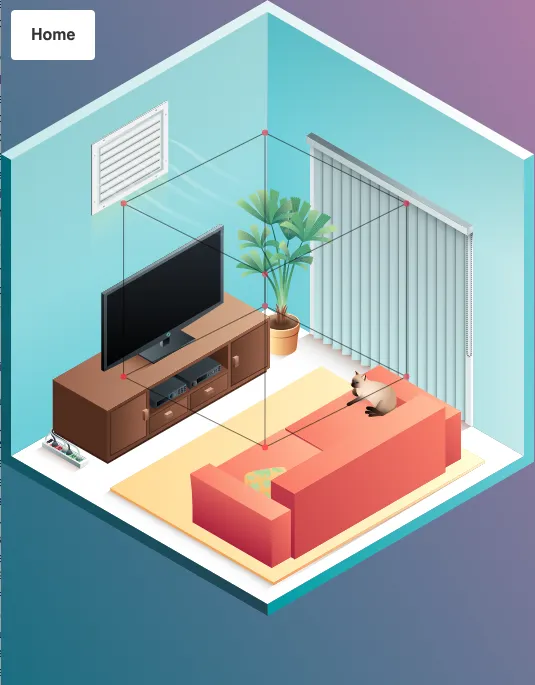

    draw();
#stage {
  background-color: cyan;
 }
<canvas id="stage" height='500px' width='500px'></canvas>

编辑:我应该包含一张图片来更好地解释我想要实现的内容。我有一张等轴测图(45度,30度)的房间图片,并且我在上面叠加了一个画布,以便我可以在其上绘制立方体。正如你所看到的那样,它略微偏离了,我认为这是两个旋转的复合效果,因为每个函数都会改变原始节点坐标。

enter image description here


我通过将X旋转(Math.atan(-1/Math.sqrt(2)))而不是(Math.PI/6)获得了期望的效果。但我不明白为什么。 - Ashbury
你想让边缘与水平之间的角度为30度,但这并不意味着你要旋转30度。维基百科在这里解释:https://en.wikipedia.org/wiki/Isometric_projection#Rotation_angles - Peter Collingridge
2个回答

2

你需要投影而非旋转

你的问题在于你试图使用变换矩阵来应用投影。

变换矩阵将保持盒子的原始形状,每个轴都与其他轴成90度角。

你想让一个轴呈45度,另一个轴呈30度。仅凭旋转无法实现这一点。

投影矩阵

基本的3x4矩阵表示4个3D向量。这些向量是3D空间中x、y、z轴的方向和比例,第4个向量是原点。

投影矩阵移除了z部分,将坐标转换为2D空间。每个轴的z部分都为0。

由于等轴投影是平行的,我们可以创建一个矩阵,在画布上设置2D轴方向。

x轴为45度。

const xAxis = Math.PI * ( 1 /  4);
iso.x.set(Math.cos(xAxis), Math.sin(xAxis), 0);

120度的y轴

const yAxis = Math.PI * ( 4 / 6);
iso.y.set(Math.cos(yAxis), Math.sin(yAxis), 0);

而且还有垂直于页面向上的z轴
iso.z.set(0,-1,0);

转换

然后,我们只需将每个顶点坐标乘以相应的轴。

// m is the matrix (iso)
// a is vertex in
// b is vertex out
// m.o is origin (not used in this example
b.x = a.x * m.x.x + a.y * m.y.x + a.z * m.z.x + m.o.x;
b.y = a.x * m.x.y + a.y * m.y.y + a.z * m.z.y + m.o.y;
b.z = a.x * m.x.z + a.y * m.y.z + a.z * m.z.z + m.o.z;
//    ^^^^^^^^^^^   ^^^^^^^^^^^   ^^^^^^^^^^^  
//    move x dist   move y dist   move z dist
//    along x axis  along y axis  along y axis
//     45deg          120deg        Up -90deg

以上代码的示例

我在片段中提供了一个非常基本的矩阵作为参考。

该片段使用您的近似布局创建 3D 对象。

变换需要第二个对象来获得结果。

我还添加了一个名为projectIso的函数,它接受 x、y、z 轴的方向和 x、y、z 轴的比例,并按上述概述创建投影矩阵。

因此,以上操作可通过以下方式完成:

const mat = Mat().projectIso(
    Math.PI * ( 1 / 4), 
    Math.PI * ( 4 / 6),
    Math.PI * ( 3 / 2)  // up
); // scales default to 1

const ctx = canvas.getContext('2d');

var w = canvas.width;
var h = canvas.height;
var cw = w / 2;  // center 
var ch = h / 2;

const V = (x,y,z) => ({x,y,z,set(x,y,z){this.x = x;this.y = y; this.z = z}});
const Mat = () => ( {
   x : V(1,0,0),
   y : V(0,1,0),
   z : V(0,0,1),
   o : V(0,0,0), // origin
   ident(){
      const m = this;
      m.x.set(1,0,0);
      m.y.set(0,1,0);
      m.z.set(0,0,1);
      m.o.set(0,0,0);
      return m;
   },
   rotX(r) {
      const m = this.ident();      
      m.y.set(0, Math.cos(r), Math.sin(r));
      m.z.set(0, -Math.sin(r), Math.cos(r));
      return m;      
   },
   rotY(r) {
      const m = this.ident();      
      m.x.set(Math.cos(r), 0, Math.sin(r));
      m.z.set(-Math.sin(r), 0, Math.cos(r));
      return m;      
   },      
   rotZ(r) {
      const m = this.ident();      
      m.x.set(Math.cos(r), Math.sin(r), 0);
      m.y.set(-Math.sin(r), Math.cos(r), 0);
      return m;      
   },    
   projectIso(xAxis, yAxis, zAxis, xScale = 1, yScale = 1, zScale = 1) {
      const m = this.ident();      
      iso.x.set(Math.cos(xAxis) * xScale, Math.sin(xAxis) * xScale, 0);
      iso.y.set(Math.cos(yAxis) * yScale, Math.sin(yAxis) * yScale, 0);
      iso.z.set(Math.cos(zAxis) * zScale, Math.sin(zAxis) * zScale, 0);
      return m;
   },
   transform(obj, result){
      const m = this;
      const na = obj.nodes;
      const nb = result.nodes;
      var i = 0;
      while(i < na.length){
         const a = na[i];
         const b = nb[i++];
         b.x = a.x * m.x.x + a.y * m.y.x + a.z * m.z.x + m.o.x;
         b.y = a.x * m.x.y + a.y * m.y.y + a.z * m.z.y + m.o.y;
         b.z = a.x * m.x.z + a.y * m.y.z + a.z * m.z.z + m.o.z;
      }
      return result;
   }
});

// create a box
const Box = (size = 35) =>( {
  nodes: [
    V(-size, -size, -size),
    V(-size, -size, size),
    V(-size, size, -size),
    V(-size, size, size),
    V(size, -size, -size),
    V(size, -size, size),
    V(size, size, -size),
    V(size, size, size),
  ],
  edges: [[0, 1],[1, 3],[3, 2],[2, 0],[4, 5],[5, 7],[7, 6],[6, 4],[0, 4],[1, 5],[2, 6],[3, 7]],
});

// draws a obj that has nodes, and edges

function draw(obj) {
    ctx.fillStyle = 'red';
  const edges =  obj.edges;
  const nodes =  obj.nodes;
  var i = 0;
  ctx.beginPath();
  while(i < edges.length){
    var edge = edges[i++];
    ctx.moveTo(nodes[edge[0]].x, nodes[edge[0]].y);
    ctx.lineTo(nodes[edge[1]].x, nodes[edge[1]].y);
    
  }
  ctx.stroke();    
  i = 0;
  ctx.beginPath();
  while(i < nodes.length){
    const x = nodes[i].x;
    const y = nodes[i++].y;
    ctx.moveTo(x+3,y);
    ctx.arc(x,y, 3, 0, 2 * Math.PI, false);
  }
  ctx.fill();
}

// create boxes (box1 is the projected result)
var box = Box();
var box1 = Box();
var box2 = Box();

// create the projection matrix
var iso = Mat();
// angles for X, and Y axis
const xAxis = Math.PI * ( 1 / 4);
const yAxis = Math.PI * ( 4 / 6);
iso.x.set(Math.cos(xAxis), Math.sin(xAxis),0);
iso.y.set(Math.cos(yAxis), Math.sin(yAxis), 0);
// the direction of Z
iso.z.set(0, -1, 0);

// center rendering
    
ctx.setTransform(1,0,0,1,cw* 0.5,ch);

// transform and render
draw(iso.transform(box,box1));

iso.projectIso(Math.PI * ( 1 / 6), Math.PI * ( 5 / 6), -Math.PI * ( 1 / 2))
ctx.setTransform(1,0,0,1,cw* 1,ch);
draw(iso.transform(box,box1));

iso.rotY(Math.PI / 4);
iso.transform(box,box1);
iso.rotX(Math.atan(1/Math.SQRT2));
iso.transform(box1,box2);
ctx.setTransform(1,0,0,1,cw* 1.5,ch);
draw(box2);
<canvas id="canvas" height='200' width='500'></canvas>


非常有用的,我正在学习我们方法之间的区别。我更新了最初的问题,因为我没有正确地表达我想要实现的结果。我试图将立方体与背景(包括图片)匹配,该背景呈45度水平和30度垂直。 - Ashbury
@Ashbury 我的代码中有两个错别字,影响了projectIso函数。我已经修复了它,并且演示在片段的最后三行中呈现了你想要的投影效果。X为30度(其中0度是从左到右的水平线),Y为150度,Z仍为-90度。 - Blindman67

1
我认为问题可能在于房间绕x轴的旋转不是30度。在等角图像中,一个立方体的侧面和水平面之间通常存在30度的角度。但是为了得到这个水平角度,绕x轴的旋转应该约为35度(atan(1/sqrt(2)))。请参阅维基百科文章中的概述
话虽如此,有时在计算机图形中,立方体的侧面与水平面之间的角度约为27度(atan(0.5)),因为这会在计算机屏幕上产生更整洁的光栅线条。在这种情况下,绕x轴的旋转确实是30度。查看本文以获取有关不同投影类型的更多信息。

如果您测量给定图像的像素大小,则位于顶部角落的三角形为266px x 154px像素,对角线长度为306px,与墙高度相匹配。x和y轴的角度为asin(154 / 266) 30度和150度。这具有立方体的近角和远角重叠,并占据一个六边形,内角为120度,总高度为墙高度的两倍306 * 2 = 616px(在这种投影类型中存在一个像素偏移,测得的高度为615px)。 - Blindman67
1
因此,如果图片中x轴的角度为30度,则需要通过atan(1 / sqrt(2))旋转立方体才能获得该角度。 - Peter Collingridge
抱歉,但“通过atan(1 / sqrt(2))旋转立方体”是无意义的。立方体是三维的,旋转需要一个旋转轴。但即使如此,也不会起作用,因为所需的不是旋转。所需的投影具有x轴为30度,y轴为150度和z轴为-90度。该框被扭曲以适应投影的要求。请参见我的代码片段,右侧的框是OP所追求的投影。 - Blindman67
旋转是关于x轴的,就像我在我的答案中所说的那样。这篇维基百科文章解释了为什么旋转角度约为35度而不是30度:https://en.wikipedia.org/wiki/Isometric_projection#Rotation_angles - Peter Collingridge
你不应该在计算机图形学中使用它,因为它会将投影的大小缩小约80%,并且由于像素查找(双线性或最近)而导致伪影,并且只使用了64%的像素,浪费内存。我概述的方法保持1:1的像素比例。如果您映射一个100x100的图像,则三个可见面的总面积为30000px。(请参见我的答案,右侧第三个投影是通过维基方法实现的) - Blindman67
这一切都是真的,但问题是为什么盒子没有与房间对齐,答案是因为他旋转的角度不正确。他甚至在他的问题上留下了一个评论,说通过 atan(1/sqrt(2)) 旋转可以解决问题。 - Peter Collingridge

网页内容由stack overflow 提供, 点击上面的
可以查看英文原文,
原文链接