感谢ybungalobill的帮助,我做了以下操作使其正常工作:
- 使用以下代码从原始高度图(对称网格)创建了一张普通地图:
从高度图计算法线
public void calcNormals() {
Vec3 up = new Vec3(0, 1, 0);
float sizeFactor = 1.0f / (8.0f * cellSize);
normals = new Vec3[rows * cols];
for (int row = 0; row < rows; row++) {
for (int col = 0; col < cols; col++) {
Vec3 normal = up;
if (col > 0 && row > 0 && col < cols - 1 && row < rows - 1) {
float nw = getValue(row - 1, col - 1);
float n = getValue(row - 1, col);
float ne = getValue(row - 1, col + 1);
float e = getValue(row, col + 1);
float se = getValue(row + 1, col + 1);
float s = getValue(row + 1, col);
float sw = getValue(row + 1, col - 1);
float w = getValue(row, col - 1);
float dydx = ((ne + 2 * e + se) - (nw + 2 * w + sw)) * sizeFactor;
float dydz = ((sw + 2 * s + se) - (nw + 2 * n + ne)) * sizeFactor;
normal = new Vec3(-dydx, 1.0f, -dydz).getUnitVector();
}
normals[row * cols + col] = normal;
}
}
}
从法线图创建图像
public static BufferedImage getNormalMap(Terrain terrain) {
    Vec3[] normals = terrain.getNormals();
    float[] pixels = new float[normals.length * 3];

    for (int i = 0; i < normals.length; i++) {
        Vec3 normal = normals[i];
        float x = (1.0f + normal.x) * 0.5f;
        float y = (1.0f + normal.y) * 0.5f;
        float z = (1.0f + normal.z) * 0.5f;
        pixels[i * 3] = x * MAX;
        pixels[i * 3 + 1] = y * MAX;
        pixels[i * 3 + 2] = z * MAX;
    }

    BufferedImage img = new BufferedImage(cols, rows, BufferedImage.TYPE_INT_RGB);
    WritableRaster imgRaster = img.getRaster();
    imgRaster.setPixels(0, 0, cols, rows, pixels);
    return img;
}
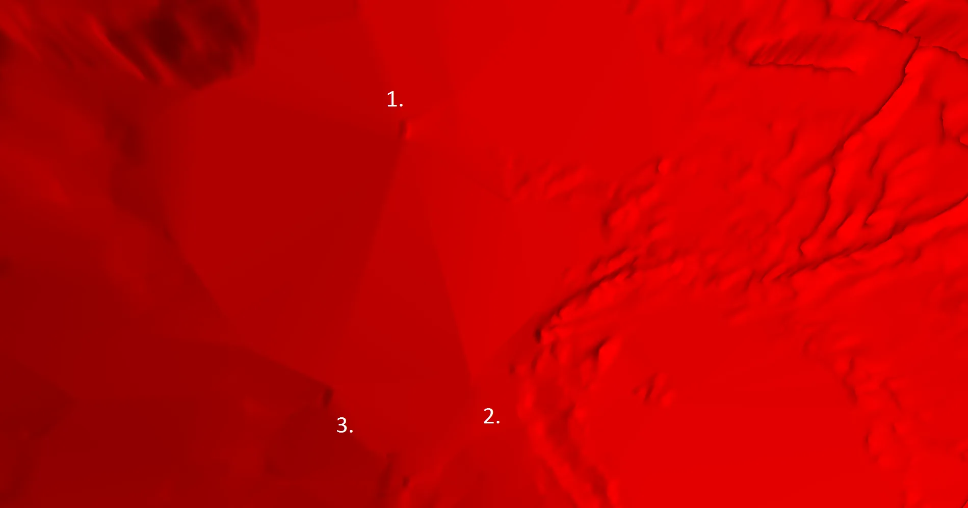
应用图像到片元着色器中,并使用顶点着色器中的顶点位置计算纹理坐标:
- 在片元着色器中应用图像并使用顶点着色器中的顶点位置计算纹理坐标:
片元着色器的一部分:
void main() {
    vec3 newNormal = texture(normalMap, vec2(worldPos0.x / maxX, worldPos0.z / maxZ)).xyz;
    newNormal = (2.0 * newNormal) - 1.0;
    outputColor = calcColor(normalize(newNormal));
}
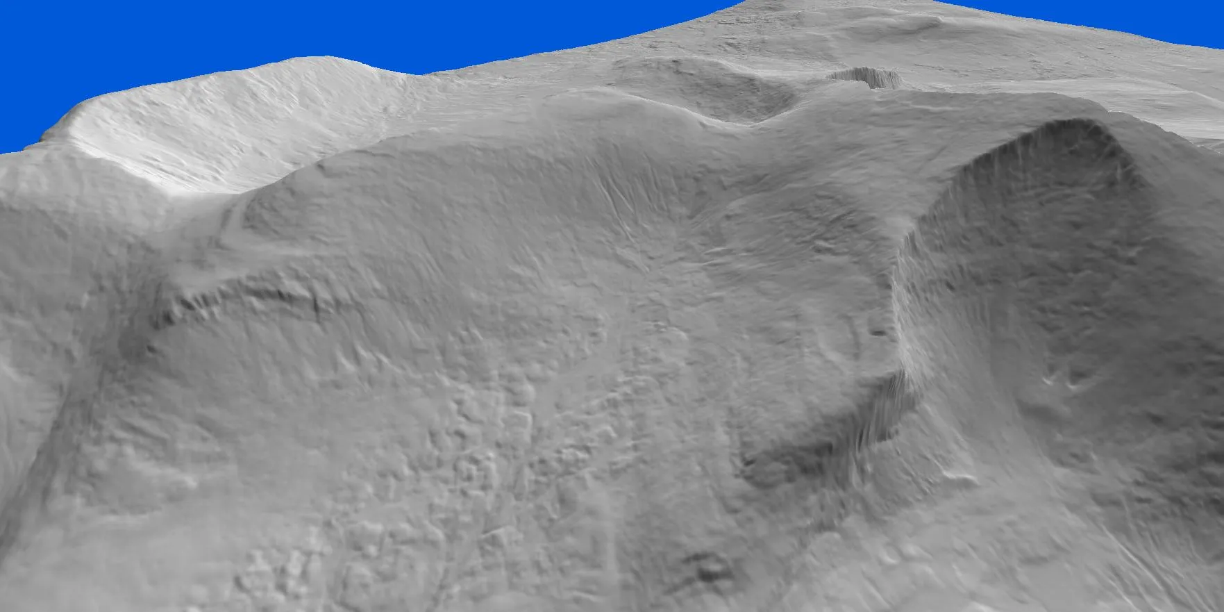
结果如下:
以下是结果:
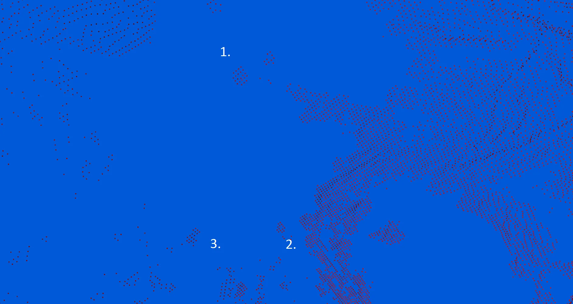
使用点渲染的相同视图:
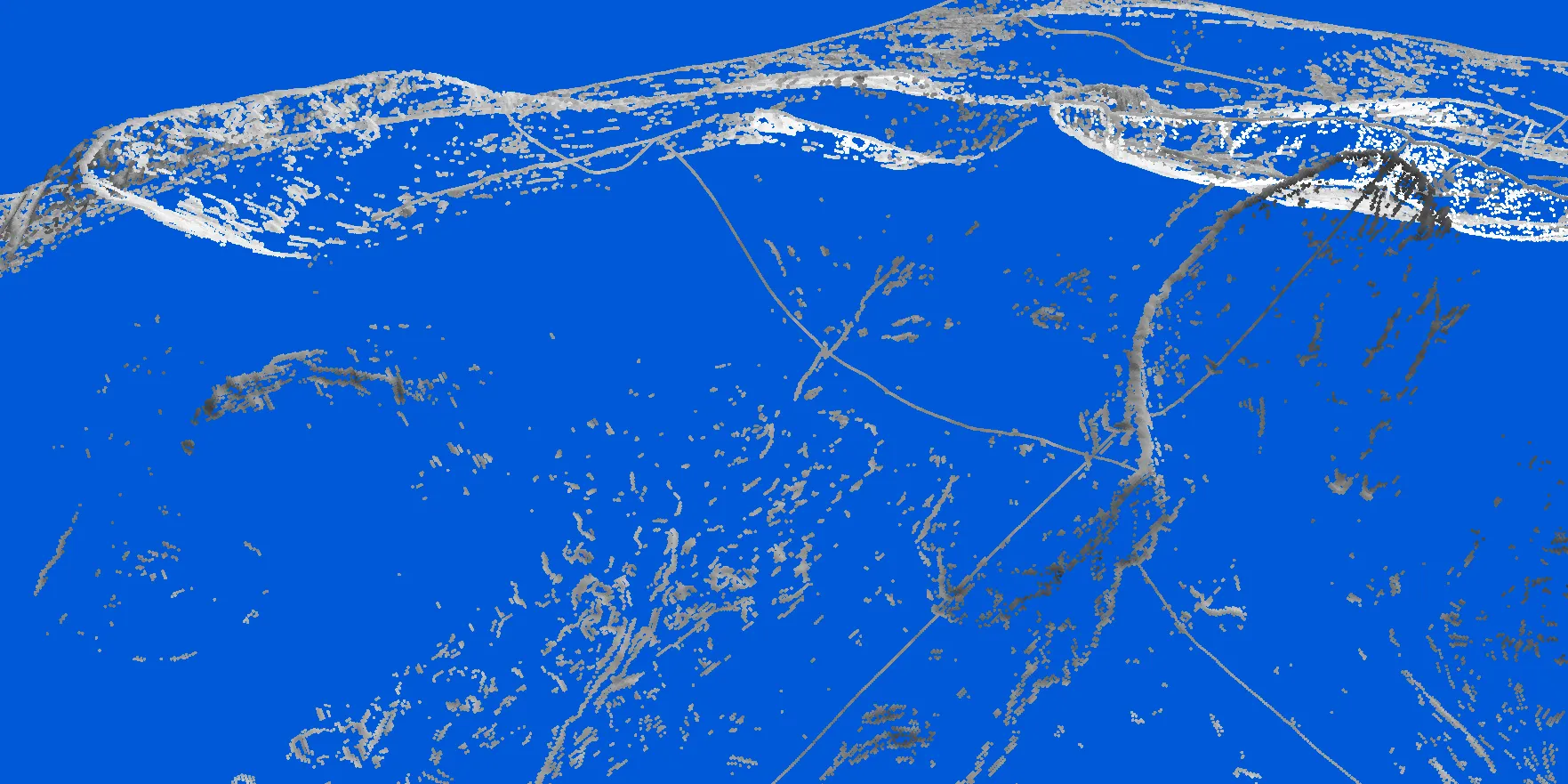
换句话说:少量顶点,但地形细节高。