Win 7,x64,Python 2.7
我试图旋转一个最初位于xz平面上的正方形,使其法线与给定的3D向量对齐。同时,我将正方形平移到向量的起点,但这不是问题。
我采取的方法如下:
1)通过给定向量和正方形的法线(在本例中为y方向的单位向量)的叉积找到旋转轴。
2)通过给定向量和正方形的法线的点积找到旋转角度。
3)构建适当的旋转矩阵。
4)将旋转矩阵应用到正方形的顶点上。
5)平移到给定向量的起点。
代码...
import numpy as np
import matplotlib.pyplot as plt
from mpl_toolkits.mplot3d import Axes3D
import math

fig = plt.figure()
ax = fig.add_subplot(111, projection='3d')
na = np.array

def rotation_matrix(axis, theta):
    """
    Return the rotation matrix associated with counterclockwise rotation about
    the given axis by theta radians.
    """
    axis = np.asarray(axis)
    axis = axis/math.sqrt(np.dot(axis, axis))
    a = math.cos(theta/2.0)
    b, c, d = -axis*math.sin(theta/2.0)
    aa, bb, cc, dd = a*a, b*b, c*c, d*d
    bc, ad, ac, ab, bd, cd = b*c, a*d, a*c, a*b, b*d, c*d
    return np.array([[aa+bb-cc-dd, 2*(bc+ad), 2*(bd-ac)],
                     [2*(bc-ad), aa+cc-bb-dd, 2*(cd+ab)],
                     [2*(bd+ac), 2*(cd-ab), aa+dd-bb-cc]])


edgeLen = 4.0                 # length of square side
pos = na([2.0,2.0,2.0])       # starting point of vector
dirc = na([6.0,6.0,6.0])      # direction of vector

Ux = na([1.0,0.0,0.0])      # unit basis vectors
Uy = na([0.0,1.0,0.0])
Uz = na([0.0,0.0,1.0])

x = pos[0]
y = pos[1]
z = pos[2]

# corner vertices of square in xz plane
verts = na([[edgeLen/2.0, 0, edgeLen/2.0],
            [edgeLen/2.0, 0, -edgeLen/2.0],
            [-edgeLen/2.0, 0, -edgeLen/2.0],
            [-edgeLen/2.0, 0, edgeLen/2.0]])

# For axis & angle of rotation
dirMag = np.linalg.norm(dirc)
axR = np.cross(dirc, Uy)
theta = np.arccos((np.dot(dirc, Uy) / dirMag))

Rax = rotation_matrix(axR, theta)   # rotation matrix

# rotate vertices
rotVerts = na([0,0,0])

for v in verts:

    temp = np.dot(Rax, v)
    temp = na([temp[0]+x, temp[1]+y, temp[2]+z])
    rotVerts = np.vstack((rotVerts, temp))

rotVerts = np.delete(rotVerts, rotVerts[0], axis=0)

# plot
# oringinal square
ax.scatter(verts[:,0], verts[:,1], verts[:,2], s=10, c='r', marker='o')
ax.plot([verts[0,0], verts[1,0]], [verts[0,1], verts[1,1]], [verts[0,2], verts[1,2]], color='g', linewidth=1.0)
ax.plot([verts[1,0], verts[2,0]], [verts[1,1], verts[2,1]], [verts[1,2], verts[2,2]], color='g', linewidth=1.0)
ax.plot([verts[2,0], verts[3,0]], [verts[2,1], verts[3,1]], [verts[2,2], verts[3,2]], color='g', linewidth=1.0)
ax.plot([verts[0,0], verts[3,0]], [verts[0,1], verts[3,1]], [verts[0,2], verts[3,2]], color='g', linewidth=1.0)

# rotated & translated square
ax.scatter(rotVerts[:,0], rotVerts[:,1], rotVerts[:,2], s=10, c='b', marker='o')
ax.plot([rotVerts[0,0], rotVerts[1,0]], [rotVerts[0,1], rotVerts[1,1]], [rotVerts[0,2], rotVerts[1,2]], color='b', linewidth=1.0)
ax.plot([rotVerts[1,0], rotVerts[2,0]], [rotVerts[1,1], rotVerts[2,1]], [rotVerts[1,2], rotVerts[2,2]], color='b', linewidth=1.0)
ax.plot([rotVerts[2,0], rotVerts[3,0]], [rotVerts[2,1], rotVerts[3,1]], [rotVerts[2,2], rotVerts[3,2]], color='b', linewidth=1.0)
ax.plot([rotVerts[0,0], rotVerts[3,0]], [rotVerts[0,1], rotVerts[3,1]], [rotVerts[0,2], rotVerts[3,2]], color='b', linewidth=1.0)

# vector
ax.plot([pos[0], pos[0]+dirc[0]], [pos[1], pos[1]+dirc[1]], [pos[1], pos[1]+dirc[1]], color='r', linewidth=1.0)

ax.set_xlabel('X axis')
ax.set_ylabel('Y axis')
ax.set_zlabel('Z axis')
这将产生以下输出..
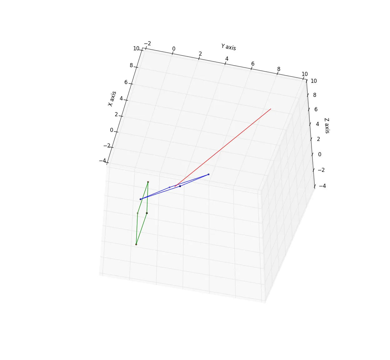 绿色正方形是xz平面上的原始图像,蓝色正方形是变换后的正方形,给定向量为红色。
如您所见,它很偏离。经过长时间浏览类似的问题和回答后,我仍然不知道为什么这不起作用。
那么我在这里错过了什么?
编辑:在评论中由El Dude提供的Euler Angles link后,我尝试了以下操作....
使用参考系xyz的yz平面中的正方形,并具有基向量Ux,Uy和Uz
将方向向量“dirVec”用作我要将正方形旋转到其中的平面的法线。
我决定使用x约定和ZXZ旋转矩阵,如Euler angles链接中所述。
我采取的步骤:
1)创建一个以Tx、Ty和Tz为基向量的旋转框架;
Tx = dirVec
Ty = Tx cross Uz (Tx not allowed to parallel to Uz)
Tz = Ty cross Tx
2) 定义一个节点线,它是沿着平面UxUy和TxTy的交线的向量,通过取Uz和Tz的叉积来定义。
3) 根据上述链接中的定义,定义了欧拉角。
4) 根据上述链接中的定义,定义了ZXZ旋转矩阵。
5) 将旋转矩阵应用于正方形顶点的坐标。
它不起作用,发生了一些奇怪的事情,无论'dirVec'的值为何,alpha始终为0。
我是否错过了一些明显的东西?
下面是修改后的代码...
import numpy as np
import matplotlib.pyplot as plt
from mpl_toolkits.mplot3d import Axes3D
import math

fig = plt.figure()
ax = fig.add_subplot(111, projection='3d')
na = np.array

def rotation_ZXZ(alpha=0.0, beta=0.0, gamma=0.0):
    """
    Return ZXZ rotaion matrix
    """
    a = alpha
    b = beta
    g = gamma

    ca = np.cos(a)
    cb = np.cos(b)
    cg = np.cos(g)

    sa = np.sin(a)
    sb = np.sin(b)
    sg = np.sin(g)

    return np.array([[(ca*cg-cb*sa*sg), (-ca*sg-cb*cg*sa), sa*sb],
                     [(cg*sa+ca*cb*sg), (ca*cb*cg-sa*sg), -ca*sb],
                     [sb*sg, cg*sb, cb]])

def rotated_axes(vector=[0,1,0]):
    """
    Return unit basis vectors for rotated frame
    """
    vx = np.asarray(vector) / np.linalg.norm(vector)

    if vx[1] != 0 or vx[2] != 0:
        U = na([1.0, 0.0, 0.0])
    else:
        U = na([0.0, 1.0, 0.0])

    vz = np.cross(vx, U)
    vz = vz / np.linalg.norm(vz)
    vy = np.cross(vx, vz)
    vy = vy / np.linalg.norm(vy)

    vx = bv(vx[0], vx[1], vx[2])
    vy = bv(vy[0], vy[1], vy[2])
    vz = bv(vz[0], vz[1], vz[2])

    return vx, vy, vz

def angle_btw_vectors(v1=[1,0,0], v2=[0,1,0]):
    """
    Return the angle, in radians, between 2 vectors
    """
    v1 = np.asarray(v1)
    v2 = np.asarray(v2)
    mags = np.linalg.norm(v1) * np.linalg.norm(v2)

    return np.arccos(np.dot(v1, v2) / mags)

edgeLen = 4.0                 # length of square side
dirVec = na([4,4,4])          # direction of given vector
pos = na([0.0, 0.0, 0.0])     # starting point of given vector
x = pos[0]
y = pos[1]
z = pos[2]

Ux = na([1,0,0])              # Unit basis vectors for static frame
Uy = na([0,1,0])
Uz = na([0,0,1])

Tx, Ty, Tz = rotated_axes(dirVec) # Unit basis vectors for rotated frame
                                  # where Tx = dirVec / |dirVec|

nodeLine = np.cross(Uz, Tz) # Node line - xy intersect XY

alpha = angle_btw_vectors(Ux, nodeLine)     #Euler angles
beta = angle_btw_vectors(Uz, Tz)
gamma = angle_btw_vectors(nodeLine, Tx)

Rzxz = rotation_ZXZ(alpha, beta, gamma)     # Rotation matrix

print '--------------------------------------'
print 'Tx: ', Tx
print 'Ty: ', Ty
print 'Tz: ', Tz
print 'Node line: ', nodeLine
print 'Tx.dirVec: ', np.dot(Tx, (dirVec / np.linalg.norm(dirVec)))
print 'Ty.dirVec: ', np.dot(Ty, dirVec)
print 'Tz.dirVec: ', np.dot(Tz, dirVec)
print '(Node Line).Tx: ', np.dot(Tx, nodeLine)
print 'alpha: ', alpha * 180 / np.pi
print 'beta: ', beta * 180 / np.pi
print 'gamma: ', gamma * 180 / np.pi
#print 'Rzxz: ', Rxzx

# corner vertices of square in yz plane
verts = na([[0, edgeLen/2.0, edgeLen/2.0],
            [0, edgeLen/2.0, -edgeLen/2.0],
            [0, -edgeLen/2.0, -edgeLen/2.0],
            [0, -edgeLen/2.0, edgeLen/2.0]])

rotVerts = na([0,0,0])
for v in verts:

    temp = np.dot(Rzxz, v)
    temp = na([temp[0]+x, temp[1]+y, temp[2]+z])
    rotVerts = np.vstack((rotVerts, temp))

rotVerts = np.delete(rotVerts, rotVerts[0], axis=0)


# plot
# oringinal square
ax.scatter(verts[:,0], verts[:,1], verts[:,2], s=10, c='g', marker='o')
ax.plot([verts[0,0], verts[1,0]], [verts[0,1], verts[1,1]], [verts[0,2], verts[1,2]], color='g', linewidth=1.0)
ax.plot([verts[1,0], verts[2,0]], [verts[1,1], verts[2,1]], [verts[1,2], verts[2,2]], color='g', linewidth=1.0)
ax.plot([verts[2,0], verts[3,0]], [verts[2,1], verts[3,1]], [verts[2,2], verts[3,2]], color='g', linewidth=1.0)
ax.plot([verts[0,0], verts[3,0]], [verts[0,1], verts[3,1]], [verts[0,2], verts[3,2]], color='g', linewidth=1.0)

# rotated & translated square
ax.scatter(rotVerts[:,0], rotVerts[:,1], rotVerts[:,2], s=10, c='b', marker='o')
ax.plot([rotVerts[0,0], rotVerts[1,0]], [rotVerts[0,1], rotVerts[1,1]], [rotVerts[0,2], rotVerts[1,2]], color='b', linewidth=1.0)
ax.plot([rotVerts[1,0], rotVerts[2,0]], [rotVerts[1,1], rotVerts[2,1]], [rotVerts[1,2], rotVerts[2,2]], color='b', linewidth=1.0)
ax.plot([rotVerts[2,0], rotVerts[3,0]], [rotVerts[2,1], rotVerts[3,1]], [rotVerts[2,2], rotVerts[3,2]], color='b', linewidth=1.0)
ax.plot([rotVerts[0,0], rotVerts[3,0]], [rotVerts[0,1], rotVerts[3,1]], [rotVerts[0,2], rotVerts[3,2]], color='b', linewidth=1.0)

# Rotated reference coordinate system
ax.plot([pos[0], pos[0]+Tx[0]], [pos[1], pos[1]+Tx[1]], [pos[2], pos[2]+Tx[2]], color='r', linewidth=1.0)
ax.plot([pos[0], pos[0]+Ty[0]], [pos[1], pos[1]+Ty[1]], [pos[1], pos[2]+Ty[2]], color='b', linewidth=1.0)
ax.plot([pos[0], pos[0]+Tz[0]], [pos[1], pos[1]+Tz[1]], [pos[1], pos[2]+Tz[2]], color='g', linewidth=1.0)

ax.set_xlabel('X axis')
ax.set_ylabel('Y axis')
ax.set_zlabel('Z axis')