我想分享一下我对此转换的MATLAB实现。我还参考了OpenGL 4.1规范第3.8.10章节(
在这里找到)以及Paul Bourke的网站(
在这里找到)。确保您查看子标题:
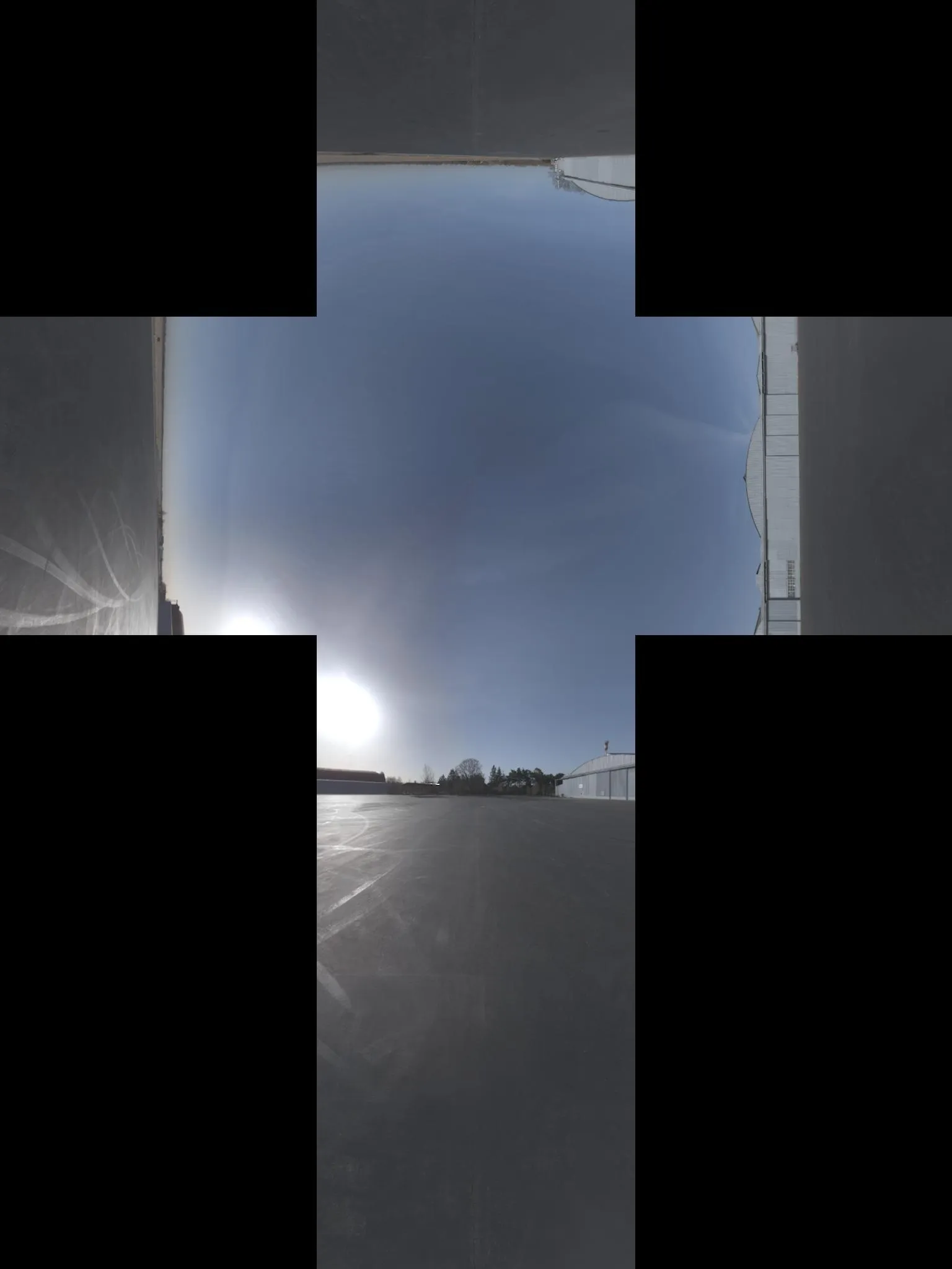
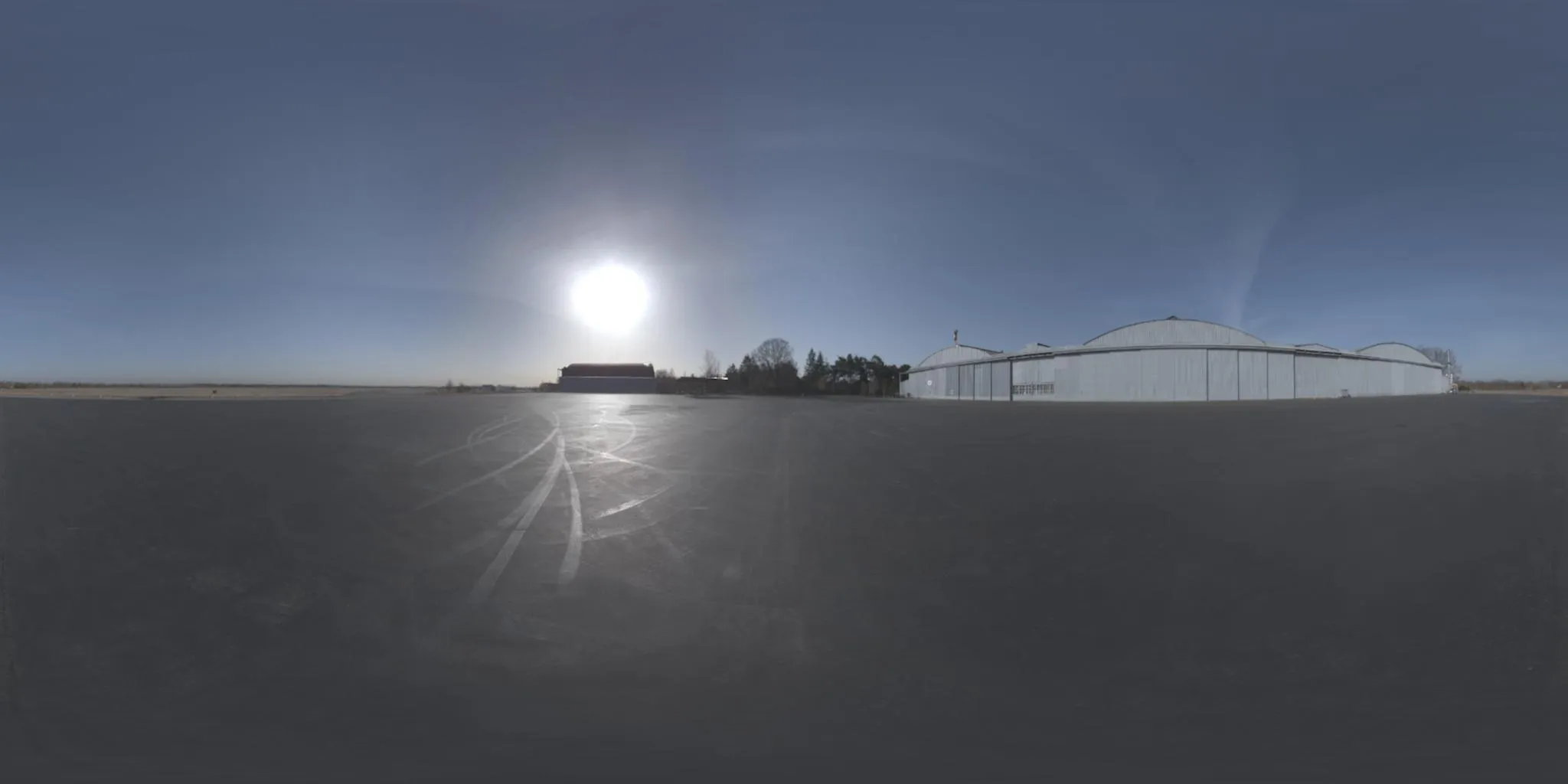
将6个立方体环境贴图和一个球形贴图相互转换。
我还受到上面Sambatyon帖子的启发。它最初是从Python移植到MATLAB,但我使代码完全矢量化(即没有
for循环)。我还将立方体图像分成了6个单独的图像,因为我正在构建的应用程序中立方体图像是以这种格式呈现的。此外,代码中没有错误检查,并且假定所有立方体图像都具有相同的大小(
n x n)。这也假设图像是以RGB格式呈现的。如果您想为单色图像执行此操作,只需注释掉需要访问多个通道的那些代码行即可。我们开始吧!
function [out] = cubic2equi(top, bottom, left, right, front, back)
height = size(top, 1);
width = 2*height;
FACE_Z_POS = 1;
FACE_Z_NEG = 2;
FACE_Y_POS = 3;
FACE_Y_NEG = 4;
FACE_X_NEG = 5;
FACE_X_POS = 6;
stackedImages{FACE_Z_POS} = left;
stackedImages{FACE_Z_NEG} = right;
stackedImages{FACE_Y_POS} = top;
stackedImages{FACE_Y_NEG} = bottom;
stackedImages{FACE_X_NEG} = front;
stackedImages{FACE_X_POS} = back;
imagesRed = uint8(zeros(height, height, 6));
imagesGreen = uint8(zeros(height, height, 6));
imagesBlue = uint8(zeros(height, height, 6));
for i = 1 : 6
im = stackedImages{i};
imagesRed(:,:,i) = im(:,:,1);
imagesGreen(:,:,i) = im(:,:,2);
imagesBlue(:,:,i) = im(:,:,3);
end
[X, Y] = meshgrid(1:width, 1:height);
Y = 2*Y/height - 1;
X = 2*X/width - 1;
sphereTheta = X*pi;
spherePhi = (pi/2)*Y;
texX = cos(spherePhi).*cos(sphereTheta);
texY = sin(spherePhi);
texZ = cos(spherePhi).*sin(sphereTheta);
comp = cat(3, texX, texY, texZ);
[~,ind] = max(abs(comp), [], 3);
maxVal = zeros(size(ind));
maxVal(ind == 1) = texX(ind == 1);
maxVal(ind == 2) = texY(ind == 2);
maxVal(ind == 3) = texZ(ind == 3);
getFace = -1*ones(size(maxVal));
ind = abs(maxVal - texX) < 0.00001 & texX < 0;
getFace(ind) = FACE_X_POS;
ind = abs(maxVal - texX) < 0.00001 & texX >= 0;
getFace(ind) = FACE_X_NEG;
ind = abs(maxVal - texY) < 0.00001 & texY < 0;
getFace(ind) = FACE_Y_POS;
ind = abs(maxVal - texY) < 0.00001 & texY >= 0;
getFace(ind) = FACE_Y_NEG;
ind = abs(maxVal - texZ) < 0.00001 & texZ < 0;
getFace(ind) = FACE_Z_POS;
ind = abs(maxVal - texZ) < 0.00001 & texZ >= 0;
getFace(ind) = FACE_Z_NEG;
rawX = -1*ones(size(maxVal));
rawY = rawX;
rawZ = rawX;
ind = getFace == FACE_X_POS;
rawX(ind) = -texZ(ind);
rawY(ind) = texY(ind);
rawZ(ind) = texX(ind);
ind = getFace == FACE_X_NEG;
rawX(ind) = texZ(ind);
rawY(ind) = texY(ind);
rawZ(ind) = texX(ind);
ind = getFace == FACE_Y_POS;
rawX(ind) = texZ(ind);
rawY(ind) = texX(ind);
rawZ(ind) = texY(ind);
ind = getFace == FACE_Y_NEG;
rawX(ind) = texZ(ind);
rawY(ind) = -texX(ind);
rawZ(ind) = texY(ind);
ind = getFace == FACE_Z_POS;
rawX(ind) = texX(ind);
rawY(ind) = texY(ind);
rawZ(ind) = texZ(ind);
ind = getFace == FACE_Z_NEG;
rawX(ind) = -texX(ind);
rawY(ind) = texY(ind);
rawZ(ind) = texZ(ind);
rawCoords = cat(3, rawX, rawY, rawZ);
cubeCoordsX = ((rawCoords(:,:,1) ./ abs(rawCoords(:,:,3))) + 1) / 2;
cubeCoordsY = ((rawCoords(:,:,2) ./ abs(rawCoords(:,:,3))) + 1) / 2;
cubeCoords = cat(3, cubeCoordsX, cubeCoordsY);
normalizedX = round(cubeCoords(:,:,1) * height);
normalizedY = round(cubeCoords(:,:,2) * height);
normalizedX(normalizedX < 1) = 1;
normalizedX(normalizedX > height) = height;
normalizedY(normalizedY < 1) = 1;
normalizedY(normalizedY > height) = height;
normalizedCoords = cat(3, normalizedX, normalizedY);
out = uint8(zeros([size(maxVal) 3]));
ind = sub2ind([height height 6], normalizedCoords(:,:,2), ...
normalizedCoords(:,:,1), getFace);
out(:,:,1) = imagesRed(ind);
out(:,:,2) = imagesGreen(ind);
out(:,:,3) = imagesBlue(ind);
我还通过github公开了代码,您可以在这里找到它。包括主要的转换脚本、一个用来展示其使用的测试脚本以及从Paul Bourke的网站上获取的一组6个立方图像样本。希望这对您有用!