如何创建带有圆角的对角渐变自定义drawable?

10

我正在尝试使用XML创建自定义的可绘制对象,就像附图所示 enter image description here

以下是我尝试过的两种方法:

<?xml version="1.0" encoding="utf-8"?>
<shape xmlns:android="http://schemas.android.com/apk/res/android"
android:shape="rectangle">
<corners android:radius="30dp" />
<solid android:color="@color/colorAccent" />
<stroke
    android:width="2dp"
    android:color="@color/colorAccent" />
<gradient
    android:angle="135"
    android:endColor="#000"
    android:startColor="#ffff"
    android:type="linear" />
</shape>

按照这种方法我可以得到正确的效果,但是颜色似乎被合并了,我想要两种颜色没有任何合并效果,然后我尝试了这样做:

这样做我可以得到正确的效果,但是颜色看起来似乎混合了。我想要两种颜色而不是有任何混合效果,所以我尝试了这样做,

<?xml version="1.0" encoding="utf-8"?>
<layer-list xmlns:android="http://schemas.android.com/apk/res/android">
<item android:drawable="@color/white">
    <shape android:shape="oval">
        <corners android:radius="@dimen/size_30dp" />
    </shape>
</item>
<item>
    <rotate
        android:fromDegrees="35"
        android:pivotX="0%"
        android:pivotY="100%">
        <shape android:shape="rectangle">
            <solid android:color="@color/textColorGreyExtraLight" />
        </shape>
    </rotate>
</item>
</layer-list>

这种方法实际上搞乱了用户界面,而且我不得不妥协圆角。

那么有没有办法使用XML来绘制这个效果呢?

非常感谢任何形式的帮助。

顺便提一下可绘制对象的宽度和高度会变化,因此对角线应始终从左下角到右上角。

谢谢


你为什么要这样定义它?否则,为什么不使用矢量图像或只是 PNG? - Eselfar
是的。一个原因是,应用程序有时会更改整个主题,包括颜色,@Eselfar - Sanoop Surendran
5个回答

17

试试这个:

<?xml version="1.0" encoding="utf-8"?>
<shape xmlns:android="http://schemas.android.com/apk/res/android"
android:shape="rectangle">

<stroke android:color="#0a0909"
    android:width="2dp"/>

<corners android:radius="20dp"/>

<gradient android:angle="45"
    android:type="linear"
    android:startColor="#d61a1a"
    android:endColor="#19f269"
    android:useLevel="false"/>

<size android:height="250dp"
    android:width="250dp"/>
</shape>

你将会得到类似于这样的输出


3
看到了,Raghav,非常感谢你的努力。如果你没有仔细阅读我的问题,我想要一条对角线,而不是合并的效果。谢谢 :) - Sanoop Surendran

3
虽然您要求的是基于XML的解决方案,但我很有兴趣构建一个自定义的Drawable来解决您的问题。它基本上只是使用自定义路径绘制两个形状并在它们周围添加边框。如果您为颜色添加setter或将其作为构造函数参数,则可以获得所需的灵活性,以适应应用程序主题更改。如果XML是您选择的方式,请随意忽略此内容,我很乐意构建它。 :)
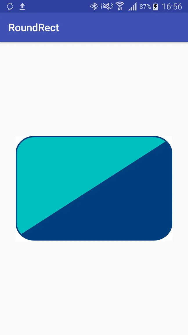
它看起来像这样:

Screenshot of custom drawable

public class CustomDrawable extends Drawable {

    private final int mBorderWidth;
    private final int mCornerRadius;

    private final Paint mBorderPaint = new Paint();
    private final Paint mTopLeftShapePaint = new Paint();
    private final Paint mBottomRightShapePaint = new Paint();

    private final RectF mBorderRect = new RectF();

    private final Path mTopLeftShapePath = new Path();
    private final Path mBottomRightShapePath = new Path();

    public CustomDrawable() {
        mBorderWidth = 8;
        mCornerRadius = 64;

        mTopLeftShapePaint.setColor(Color.parseColor("#00a2e8"));
        mTopLeftShapePaint.setStyle(Paint.Style.FILL);
        mTopLeftShapePaint.setAntiAlias(true);

        mBottomRightShapePaint.setColor(Color.parseColor("#3f48cc"));
        mBottomRightShapePaint.setStyle(Paint.Style.FILL);
        mBottomRightShapePaint.setAntiAlias(true);

        mBorderPaint.setColor(Color.parseColor("#3f48cc"));
        mBorderPaint.setStyle(Paint.Style.STROKE);
        mBorderPaint.setStrokeWidth(mBorderWidth);
        mBorderPaint.setAntiAlias(true);
    }

    @Override
    protected void onBoundsChange(Rect bounds) {
        super.onBoundsChange(bounds);

        mBorderRect.set(bounds);
        mBorderRect.inset(mBorderWidth / 2, mBorderWidth / 2);

        calculatePaths();
    }

    private void calculatePaths() {
        // Calculate position of the four corners
        RectF topLeftCorner = new RectF(mBorderRect.left, mBorderRect.top, mBorderRect.left + 2 * mCornerRadius, mBorderRect.top + 2 * mCornerRadius);
        RectF topRightCorner = new RectF(mBorderRect.right - 2 * mCornerRadius, mBorderRect.top, mBorderRect.right, mBorderRect.top + 2 * mCornerRadius);
        RectF bottomLeftCorner = new RectF(mBorderRect.left, mBorderRect.bottom - 2 * mCornerRadius, mBorderRect.left + 2 * mCornerRadius, mBorderRect.bottom);
        RectF bottomRightCorner = new RectF(mBorderRect.right - 2 * mCornerRadius, mBorderRect.bottom - 2 * mCornerRadius, mBorderRect.right, mBorderRect.bottom);

        // Calculate position of intersections of diagonal line and top-right / bottom-left corner
        PointF topRightCornerIntersection = calculateCircleCoordinate(topRightCorner.centerX(), topRightCorner.centerY(), 315);
        PointF bottomLeftCornerIntersection = calculateCircleCoordinate(bottomLeftCorner.centerX(), bottomLeftCorner.centerY(), 135);

        // Build top left shape
        mTopLeftShapePath.reset();
        mTopLeftShapePath.moveTo(topLeftCorner.left, topLeftCorner.centerY());
        mTopLeftShapePath.lineTo(bottomLeftCorner.left, bottomLeftCorner.centerY());
        mTopLeftShapePath.arcTo(bottomLeftCorner, -180, -45, false);
        mTopLeftShapePath.lineTo(topRightCornerIntersection.x, topRightCornerIntersection.y);
        mTopLeftShapePath.arcTo(topRightCorner, -45, -45, false);
        mTopLeftShapePath.lineTo(topLeftCorner.centerX(), topLeftCorner.top);
        mTopLeftShapePath.arcTo(topLeftCorner, -90, -90, false);

        // Build bottom right shape
        mBottomRightShapePath.reset();
        mBottomRightShapePath.moveTo(bottomLeftCorner.centerX(), bottomLeftCorner.bottom);
        mBottomRightShapePath.lineTo(bottomRightCorner.centerX(), bottomRightCorner.bottom);
        mBottomRightShapePath.arcTo(bottomRightCorner, 90, -90, false);
        mBottomRightShapePath.lineTo(topRightCorner.right, topRightCorner.centerY());
        mBottomRightShapePath.arcTo(topRightCorner, 0, -45, false);
        mBottomRightShapePath.lineTo(bottomLeftCornerIntersection.x, bottomLeftCornerIntersection.y);
        mBottomRightShapePath.arcTo(bottomLeftCorner, 135, -45, false);
    }

    private PointF calculateCircleCoordinate(float centerX, float centerY, double angdeg) {
        double angle = Math.toRadians(angdeg);
        double x = centerX + mCornerRadius * Math.cos(angle);
        double y = centerY + mCornerRadius * Math.sin(angle);
        return new PointF((float) x, (float) y);
    }

    @Override
    public void draw(@NonNull Canvas canvas) {
        canvas.drawPath(mTopLeftShapePath, mTopLeftShapePaint);
        canvas.drawPath(mBottomRightShapePath, mBottomRightShapePaint);
        canvas.drawRoundRect(mBorderRect, mCornerRadius, mCornerRadius, mBorderPaint);
    }

    @Override
    public void setAlpha(int alpha) {
    }

    @Override
    public void setColorFilter(@Nullable ColorFilter colorFilter) {
    }

    @Override
    public int getOpacity() {
        return PixelFormat.UNKNOWN;
    }
}

免责声明:此快速草稿不包括边缘情况,例如给定视图边界太大的角半径。

看起来很有前途!但我有一个疑问,如何将它附加到我的布局上? - Sanoop Surendran
很遗憾,在布局资源XML中无法访问自定义的Drawable,您必须使用ImageView#setImageDrawable(new CustomDrawable())在程序中设置它。 - Henning Dodenhof

1
我有一个库可以做到这一点。基本上,我画了两个三角形,你可以指定左上角到右上角或右上角到左上角的方向。


1
太棒了!!不过我有一个建议,我不知道是否已经可以实现(还没有尝试代码或查看)。可以使用可绘制对象(drawables)代替颜色吗? - Sanoop Surendran

1
似乎最简单的方法是使用SVG格式绘制背景,并直接将其用作背景,或者如果您想以编程方式更改颜色,则可以将SVG转换为矢量可绘制对象(例如使用this工具),然后用作背景。 对于您的示例 VectorDrawable ( two_colored_roundrect.xml )可能如下所示:
<?xml version="1.0" encoding="utf-8"?>
<vector xmlns:android="http://schemas.android.com/apk/res/android"
        android:width="550dp"
        android:height="390dp"
        android:viewportWidth="550"
        android:viewportHeight="390">

    <path
        android:fillColor="#00bfbf"
        android:strokeColor="#003f7f"
        android:strokeWidth="5"
        android:pathData="M1.50016,66.028801l0,0c0,-35.411501 28.03274,-64.118481
62.611443,-64.118481l28.463097,0l0,0l136.615303,0l256.152985,0c16.605011,0
32.529999,6.75751 44.274994,18.780581c11.744995,12.0231 18.338013,28.3319
18.338013,45.3379l0,160.295204l0,0l0,96.177002l0,0c0,35.410004
-28.03302,64.11499
-62.613007,64.11499l-256.152985,0l-136.615303,0l-28.463097,0c-34.578703,0
-62.611443,-28.704987 -62.611443,-64.11499l0,0l0,-96.177002l0,0l0,-160.295204z" />
    <path
        android:strokeColor="#003f7f"
        android:strokeWidth="5"
        android:pathData="M 19.5 368.149994 L 529.5 21.149994" />
    <path
        android:fillColor="#003f7f"
        android:strokeColor="#003f7f"
        android:strokeWidth="5"
        android:pathData="M529.617981,20.690901c11.744995,12.0231 18.338013,28.3319
18.338013,45.3379l0,160.295204l0,0l0,96.177002l0,0c0,35.410004
-28.03302,64.11499
-62.613007,64.11499l-256.152985,0l-136.615303,0l-28.463097,0c-17.289352,0
-32.942213,-7.176239 -44.272736,-18.778748l509.779114,-347.146349z" />
</vector>

并且布局xml文件如下:

<?xml version="1.0" encoding="utf-8"?>
<RelativeLayout
    xmlns:android="http://schemas.android.com/apk/res/android"
    xmlns:tools="http://schemas.android.com/tools"
    android:layout_width="match_parent"
    android:layout_height="match_parent"
    tools:context="{YOUR_CONTEXT}">

    <View
        android:layout_width="300dp"
        android:layout_height="200dp"
        android:layout_centerInParent="true"
        android:background="@drawable/two_colored_roundrect"
        />

</RelativeLayout>

(例如)View 的位置和尺寸,你应该得到类似于这样的结果:

Two-colored round rect background

您可以像回答this问题中的那样更改路径描边和填充的颜色。


谢谢,我会尝试并告诉你 :) 再次感谢你的努力。 - Sanoop Surendran

0

所以,根据这篇文章的说法,现在可以使用颜色资源与矢量图形一起使用了。

  1. 使用您喜欢的软件(例如Illustrator)创建所需的形状
  2. 将其导出为SVG文件
  3. 使用此工具或直接在Android Studio中将其转换为XML。

现在,您已经拥有了可绘制对象,请用要使用的资源替换所有颜色。(例如:android:fillColor="#0000" 变成 android:fillColor="@color/custom_black")。

然后,在您的ImageView中,不要使用android:src="",而是使用app:srcCompat来设置可绘制对象。

别忘了在gradle文件的defaultConfig下添加vectorDrawables.useSupportLibrary = true

我已在API 19和24上进行了测试,它可以正常工作。

编辑:我正在使用Support Library版本26.0.2


谢谢,我会尝试一下并告诉你结果。另外,你能否发布一下你收到的输出截图? - Sanoop Surendran
请问您能否发布一下您的输出截图? - Sanoop Surendran
我没有生成完全相同的输出。我尝试了另一个可用的drawable,但它的效果是一样的。你需要做的唯一一件事就是创建SVG并按照说明进行操作。显然,SVG需要与您发布的图像完全相同。 - Eselfar

网页内容由stack overflow 提供, 点击上面的
可以查看英文原文,
原文链接