Latex Tikz/Pgf用参数和数字声明形状和锚点

3

我正在使用pgf绘制一些图形,虽然我并不完全了解它的工作原理,但我已经通过文档完成了所需的操作。

\pgfdeclareshape{reg}{
  % The 'minimum width' and 'minimum height' keys, not the content, determine
  % the size
  \savedanchor\northeast{%
    \pgfmathsetlength\pgf@x{\pgfshapeminwidth}%
    \pgfmathsetlength\pgf@y{\pgfshapeminheight}%
    \pgf@x=0.11\pgf@x
    \pgf@y=0.15\pgf@y
  }
  % This is redundant, but makes some things easier:
  \savedanchor\southwest{%
    \pgfmathsetlength\pgf@x{\pgfshapeminwidth}%
    \pgfmathsetlength\pgf@y{\pgfshapeminheight}%
    \pgf@x=-0.11\pgf@x
    \pgf@y=-0.15\pgf@y
  }
  % Inherit from rectangle
  \inheritanchorborder[from=rectangle]

  % Define same anchor a normal rectangle has
  \anchor{center}{\pgfpointorigin}
  \anchor{north}{\northeast \pgf@x=0pt}
  \anchor{east}{\northeast \pgf@y=0pt}
  \anchor{south}{\southwest \pgf@x=0pt}
  \anchor{west}{\southwest \pgf@y=0pt}
  \anchor{north east}{\northeast}
  \anchor{north west}{\northeast \pgf@x=-\pgf@x}
  \anchor{south west}{\southwest}
  \anchor{south east}{\southwest \pgf@x=-\pgf@x}
  \anchor{text}{
    \pgfpointorigin
    \advance\pgf@x by -.5\wd\pgfnodeparttextbox%
    \advance\pgf@y by -.5\ht\pgfnodeparttextbox%
    \advance\pgf@y by +.5\dp\pgfnodeparttextbox%
  }

  % Define anchors for signal ports

  \anchor{CLK}{
    \pgf@process{\northeast}%
    \pgf@x=0\pgf@x%
    \pgf@y=1\pgf@y%
  }
  \anchor{PC}{
    \pgf@process{\northeast}%
    \pgf@x=-2.5\pgf@x%
    \pgf@y=0\pgf@y%
  }

  \anchor{PCS}{
    \pgf@process{\northeast}%
    \pgf@x=2.5\pgf@x%
    \pgf@y=0\pgf@y%
  }

  % Draw the rectangle box and the port labels
  \backgroundpath{
    % Rectangle box
    \pgfpathrectanglecorners{\southwest}{\northeast}

    % Drawing Triangle for clock input
    % upper left x
    \southwest \pgf@xa=\pgf@x 
    \northeast \pgf@ya=\pgf@y \pgf@yb=\pgf@y \pgf@xb=\pgf@x
    \pgf@anchor@reg@CLK
    \pgf@xc=\pgf@x \pgf@yc=\pgf@y
    \pgfmathsetlength\pgf@x{1.3ex}
    \advance\pgf@xa by .15mm
    \advance\pgf@xb by -.15mm
    \advance\pgf@yc by -\pgf@x
    \pgfpathmoveto{\pgfpoint{\pgf@xa}{\pgf@ya}}
    \pgfpathlineto{\pgfpoint{\pgf@xb}{\pgf@yb}}
    \pgfpathlineto{\pgfpoint{\pgf@xc}{\pgf@yc}}
    \pgfclosepath


    \tikzset{flip flop/port labels} % Use font from this style
    \tikz@textfont


    %Drawing CLK circuit
    \pgf@anchor@reg@CLK
    \pgf@xa=\pgf@x \pgf@ya=\pgf@y
    \pgf@xb=\pgf@x \pgf@yb=\pgf@y
    \pgfmathsetlength\pgf@x{1.8ex}
    \advance\pgf@yb by \pgf@x
    \pgfpathmoveto{\pgfpoint{\pgf@xa}{\pgf@ya}}
    \pgfpathlineto{\pgfpoint{\pgf@xb}{\pgf@yb}}
    %Draw clock label
    \pgf@anchor@reg@CLK\pgftext[base,at={\pgfpoint{\pgf@x}{\pgf@y}}]{\raisebox{2.5ex}{CLK}}

    %Drawing PC circuit
    \pgf@anchor@reg@PC
    \pgf@ya=\pgf@y \pgf@yb=\pgf@y \pgf@xa=\pgf@x
    \pgf@anchor@reg@west
    \pgf@xb=\pgf@x 
    %\pgfmathsetlength\pgf@x{2.7ex}
    %\advance\pgf@xb by \pgf@x
    \pgfpathmoveto{\pgfpoint{\pgf@xa}{\pgf@ya}}
    \pgfpathlineto{\pgfpoint{\pgf@xb}{\pgf@yb}}
    \pgf@anchor@reg@PC\pgftext[base,at={\pgfpoint{\pgf@x+0.5ex}{\pgf@y}}]{\raisebox{.5ex}{PC}}

    %Drawing PC' circuit
    \pgf@anchor@reg@PCS
    \pgf@ya=\pgf@y \pgf@yb=\pgf@y\pgf@xa=\pgf@x 
    \pgf@anchor@reg@east
    \pgf@xb=\pgf@x 
    %\pgfmathsetlength\pgf@x{2.5ex}
    %\advance\pgf@xb by \pgf@x
    \pgfpathmoveto{\pgfpoint{\pgf@xa}{\pgf@ya}}
    \pgfpathlineto{\pgfpoint{\pgf@xb}{\pgf@yb}}
    \pgf@anchor@reg@PCS\pgftext[base,at={\pgfpoint{\pgf@x}{\pgf@y}}]{\raisebox{.5ex}{PC'}}
  }

}

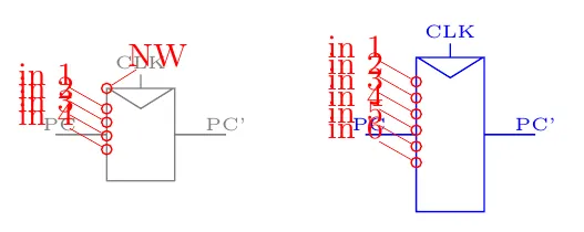
我在这里创建了一个带外部连接点的形状,其实已经很好用了。但是我真的想要在创建此形状时有一个参数,以便我可以指定端口数量。

例如像这样:

\begin{tikzpicture}
    \node [reg,black!50,ports=3] (PC) at (0,0) {};
\end{tikzpicture}

但是我在文档中找不到允许自定义参数的内容。另外,我想将锚点命名为A1、A2和A3,但似乎无法在名称中添加数字,即使在文档中明确说明像"1"和"::"这样的名称应该没有问题,但"A1"仍然会出现问题。

如果有人知道如何做到这一点,我会非常感激帮助。并且也希望有更好的参考资料来创建pgf图形。

我使用Overleaf和pdflatex编辑tex文件。

编辑: 我现在发现可以使用\pgfkeys来向图形添加参数,但它们似乎不能正常工作,而我并不真的知道该怎么处理。

\def\microarchbasekey{/tikz/microarch}
\pgfkeys{\microarchbasekey/.is family}

\pgfdeclareshape{mux}{

    \pgfkeys{\microarchbasekey,inputs/.initial=2,spacing/.initial=5}

    \savedmacro{\numpins}{
        \def\numpins{\pgfkeysvalueof{\microarchbasekey/inputs}}
    }

    \saveddimen{\spacing}{
        \pgf@x = \pgfkeysvalueof{\microarchbasekey/spacing}
    }

%a lot of code down there
}


但是它会给我返回以下错误。
A number should have been here; I inserted `0'.
(If you can't figure out why I needed to see a number,
look up `weird error' in the index to The TeXbook.)

但我找不到代码中缺失的部分。


2
我现在没有时间,但你可能会对circuitikz中的muxdemux定义感兴趣:https://github.com/circuitikz/circuitikz/blob/master/tex/pgfcircmultipoles.tex --- 它的注释不是很详细,但那里有很多锚点技巧。 - Rmano
我在 GitHub 存储库中找到了一些东西,并将它们添加到帖子中。但是我很难让它正常工作。我真的很感激您的帮助。 - MrDiver
我发布了我的方法 --- 也许有更好的方法来完成它。 - Rmano
1个回答

5

或许这是一个更适合TeX/LaTeX网站的问题,但无论如何...

关键要素如下:

  1. Add keys for the parameters. Be careful about the hierarchy, node expects keys under the /tikz family:

    %
    % better to create a family, but as an example...
    \tikzset{flip flop/port labels/.initial={\tiny}}
    %
    % number of ports
    \tikzset{ports/.initial=4}
    %
    % we need a counter
    \newcount\tmp@a
    
  2. Add stable (linked to the specific node, and not to the generic shape) parameters, all those you need to compute the position of the anchors:

    % you have to save the relevant parameters as \savedmacro
        \savedmacro\numports{
            \edef\numports{\pgfkeysvalueof{/tikz/ports}}%
        }
        % and \saveddimen
        \saveddimen\pinsdelta{
            % you can't use savedmacros nor savedanchors here (bummer!)
            \edef\numports{\pgfkeysvalueof{/tikz/ports}}%
            \pgfmathsetlength\pgf@x{0.22*\pgfshapeminheight/(\numports+1)}%
        }
    
  3. In the shape definition, you have to add the anchors with a trick --- anchors have to be added to the shape internal function. Dangerous, because the developers can change it in the future (it happened already), but I know no other way.

    % create input anchors
        % this touch internal things, so beware...
        % anchors are named pgf@anchor@<name-of-the-shape>@<name of the anchors>
        \pgfutil@g@addto@macro\pgf@sh@s@reg{%
            \tmp@a=\numports\relax
            \pgfmathloop%
            \ifnum\pgfmathcounter>\tmp@a%
            \else%
            % assign the anchor "in \pgfmathcounter" to the macro \reg@port with the number as argument
            \expandafter\xdef\csname pgf@anchor@reg@in \pgfmathcounter\endcsname{%
                \noexpand\reg@port{\pgfmathcounter}% defined below
            }%
            % \typeout{YAY\space\pgfmathcounter}
            \repeatpgfmathloop%
        }
    
  4. Define the specific functions that calculate the variable anchors. You must use only \saved... kind of parameters here, otherwise, your anchors will use the last value of the parameter, not the correct one specified with the node.

    \def\reg@port#1{%
        % this macro has the function to return the position of the anchor
        % it must use only \savedanchors and \savedmacros
        % the parameter is the number of the anchor (see above)
        \northeast
        \pgf@x=-\pgf@x
        \pgf@ya=\pgf@y
        \pgfmathsetlength{\pgf@y}{\pgf@ya-(#1+0.5)*\pinsdelta}%
    }
    

我不太明白您是如何绘制形状,以至于锚点并不在它们应该去的地方,但好吧:

输出

我的完整代码在这里:

\documentclass[border=10pt]{standalone}
\usepackage{tikz}
\makeatletter
%
% better to create a family, but as an example...
\tikzset{flip flop/port labels/.initial={\tiny}}
%
% number of ports
\tikzset{ports/.initial=4}
%
% we need a counter
\newcount\tmp@a

\pgfdeclareshape{reg}{

    % you have to save the relevant parameters as \savedmacro
    \savedmacro\numports{
        \edef\numports{\pgfkeysvalueof{/tikz/ports}}%
    }
    % and \saveddimen
    \saveddimen\pinsdelta{
        % you can't use savedmacros nor savedanchors here (bummer!)
        \edef\numports{\pgfkeysvalueof{/tikz/ports}}%
        \pgfmathsetlength\pgf@x{0.22*\pgfshapeminheight/(\numports+1)}%
    }

    % The 'minimum width' and 'minimum height' keys, not the content, determine
    % the size
    \savedanchor\northeast{%
        \pgfmathsetlength\pgf@x{\pgfshapeminwidth}%
        \pgfmathsetlength\pgf@y{\pgfshapeminheight}%
        \pgf@x=0.11\pgf@x
        \pgf@y=0.15\pgf@y
    }
    % This is redundant, but makes some things easier:
    \savedanchor\southwest{%
        \pgfmathsetlength\pgf@x{\pgfshapeminwidth}%
        \pgfmathsetlength\pgf@y{\pgfshapeminheight}%
        \pgf@x=-0.11\pgf@x
        \pgf@y=-0.15\pgf@y
    }
    % Inherit from rectangle
    \inheritanchorborder[from=rectangle]

    % Define same anchor a normal rectangle has
    \anchor{center}{\pgfpointorigin}
    \anchor{north}{\northeast \pgf@x=0pt}
    \anchor{east}{\northeast \pgf@y=0pt}
    \anchor{south}{\southwest \pgf@x=0pt}
    \anchor{west}{\southwest \pgf@y=0pt}
    \anchor{north east}{\northeast}
    \anchor{north west}{\northeast \pgf@x=-\pgf@x}
    \anchor{south west}{\southwest}
    \anchor{south east}{\southwest \pgf@x=-\pgf@x}
    \anchor{text}{
        \pgfpointorigin
        \advance\pgf@x by -.5\wd\pgfnodeparttextbox%
        \advance\pgf@y by -.5\ht\pgfnodeparttextbox%
        \advance\pgf@y by +.5\dp\pgfnodeparttextbox%
    }

    % Define anchors for signal ports

    \anchor{CLK}{
        \pgf@process{\northeast}%
        \pgf@x=0\pgf@x%
        \pgf@y=1\pgf@y%
    }
    \anchor{PC}{
        \pgf@process{\northeast}%
        \pgf@x=-2.5\pgf@x%
        \pgf@y=0\pgf@y%
    }

    \anchor{PCS}{
        \pgf@process{\northeast}%
        \pgf@x=2.5\pgf@x%
        \pgf@y=0\pgf@y%
    }

    % Draw the rectangle box and the port labels
    \backgroundpath{
        % Rectangle box
        \pgfpathrectanglecorners{\southwest}{\northeast}

        % Drawing Triangle for clock input
        % upper left x
        \southwest \pgf@xa=\pgf@x
        \northeast \pgf@ya=\pgf@y \pgf@yb=\pgf@y \pgf@xb=\pgf@x
        \pgf@anchor@reg@CLK
        \pgf@xc=\pgf@x \pgf@yc=\pgf@y
        \pgfmathsetlength\pgf@x{1.3ex}
        \advance\pgf@xa by .15mm
        \advance\pgf@xb by -.15mm
        \advance\pgf@yc by -\pgf@x
        \pgfpathmoveto{\pgfpoint{\pgf@xa}{\pgf@ya}}
        \pgfpathlineto{\pgfpoint{\pgf@xb}{\pgf@yb}}
        \pgfpathlineto{\pgfpoint{\pgf@xc}{\pgf@yc}}
        \pgfclosepath


        \tikzset{flip flop/port labels} % Use font from this style
        \tikz@textfont


        %Drawing CLK circuit
        \pgf@anchor@reg@CLK
        \pgf@xa=\pgf@x \pgf@ya=\pgf@y
        \pgf@xb=\pgf@x \pgf@yb=\pgf@y
        \pgfmathsetlength\pgf@x{1.8ex}
        \advance\pgf@yb by \pgf@x
        \pgfpathmoveto{\pgfpoint{\pgf@xa}{\pgf@ya}}
        \pgfpathlineto{\pgfpoint{\pgf@xb}{\pgf@yb}}
        %Draw clock label
        \pgf@anchor@reg@CLK\pgftext[base,at={\pgfpoint{\pgf@x}{\pgf@y}}]{\raisebox{2.5ex}{CLK}}

        %Drawing PC circuit
        \pgf@anchor@reg@PC
        \pgf@ya=\pgf@y \pgf@yb=\pgf@y \pgf@xa=\pgf@x
        \pgf@anchor@reg@west
        \pgf@xb=\pgf@x
        %\pgfmathsetlength\pgf@x{2.7ex}
        %\advance\pgf@xb by \pgf@x
        \pgfpathmoveto{\pgfpoint{\pgf@xa}{\pgf@ya}}
        \pgfpathlineto{\pgfpoint{\pgf@xb}{\pgf@yb}}
        \pgf@anchor@reg@PC\pgftext[base,at={\pgfpoint{\pgf@x+0.5ex}{\pgf@y}}]{\raisebox{.5ex}{PC}}

        %Drawing PC' circuit
        \pgf@anchor@reg@PCS
        \pgf@ya=\pgf@y \pgf@yb=\pgf@y\pgf@xa=\pgf@x
        \pgf@anchor@reg@east
        \pgf@xb=\pgf@x
        %\pgfmathsetlength\pgf@x{2.5ex}
        %\advance\pgf@xb by \pgf@x
        \pgfpathmoveto{\pgfpoint{\pgf@xa}{\pgf@ya}}
        \pgfpathlineto{\pgfpoint{\pgf@xb}{\pgf@yb}}
        \pgf@anchor@reg@PCS\pgftext[base,at={\pgfpoint{\pgf@x}{\pgf@y}}]{\raisebox{.5ex}{PC'}}
    }

    % create input anchors
    % this touch internal things, so beware...
    % anchors are named pgf@anchor@<name-of-the-shape>@<name of the anchors>
    \pgfutil@g@addto@macro\pgf@sh@s@reg{%
        \tmp@a=\numports\relax
        \pgfmathloop%
        \ifnum\pgfmathcounter>\tmp@a%
        \else%
        % assign the anchor "in \pgfmathcounter" to the macro \reg@port with the number as argument
        \expandafter\xdef\csname pgf@anchor@reg@in \pgfmathcounter\endcsname{%
            \noexpand\reg@port{\pgfmathcounter}% defined below
        }%
        % \typeout{YAY\space\pgfmathcounter}
        \repeatpgfmathloop%
    }

}
%
\def\reg@port#1{%
    % this macro has the function to return the position of the anchor
    % it must use only \savedanchors and \savedmacros
    % the parameter is the number of the anchor (see above)
    \northeast
    \pgf@x=-\pgf@x
    \pgf@ya=\pgf@y
    \pgfmathsetlength{\pgf@y}{\pgf@ya-(#1+0.5)*\pinsdelta}%
}
\makeatother

%%% handy macro to show the anchors

\def\showcoord(#1)<#2:#3>{%
    node[circle, red, draw, inner sep=1pt,pin={%
        [red, inner sep=0.5pt, font=\small,
        pin distance=#3cm, pin edge={red, }%
    ]#2:#1}](#1){}}

\begin{document}
\begin{tikzpicture}
    \node [draw,reg,minimum width=3cm, minimum height=3cm, black!50] (PC1) at (0,0) {};
    \path (PC1.north west) \showcoord(NW)<45:0.2>;
    \node [draw, reg,black!50,minimum width=3cm, minimum height=5cm, ports=6, blue] (PC2) at (3,0) {};
    \foreach \p in {1,...,4} \path(PC1.in \p) \showcoord(in \p)<145:0.3>;
    \foreach \p in {1,...,6} \path(PC2.in \p) \showcoord(in \p)<145:0.3>;
\end{tikzpicture}
\end{document}

仍然在努力理解所有这些内容,但即使我不完全明白它为什么能够工作,它似乎也是有效的。您能否推荐一些文档或网站供我查阅?(不是tikz/pgf文档)+ 非常感谢您抽出时间来撰写此文。 - MrDiver
1
@MrDiver 我不知道有其他的资源,除了源代码。我是通过TeX.stackexchange这个专门的网站上的社区学习的,那里有很多专家和友好的人(还有包的作者甚至核心开发人员)! - Rmano

网页内容由stack overflow 提供, 点击上面的
可以查看英文原文,
原文链接