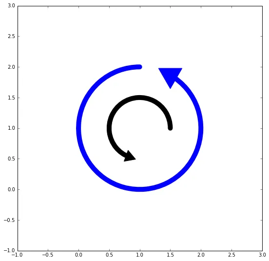
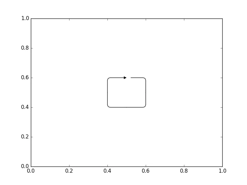
什么是在matplotlib中画一个箭头并使其回到起点指向的正确方法?我尝试过:
plt.figure()
plt.xlim([0, 1])
plt.ylim([0, 1])
plt.annotate("", xy=(0.6, 0.9),
             xycoords="figure fraction",
             xytext = (0.6, 0.8),
             textcoords="figure fraction",
             fontsize = 10, \
             color = "k",
             arrowprops=dict(edgecolor='black',
                             connectionstyle="angle,angleA=-180,angleB=45",
                             arrowstyle = '<|-',
                             facecolor="k",
                             linewidth=1,
                             shrinkA = 0,
                             shrinkB = 0))
plt.show()
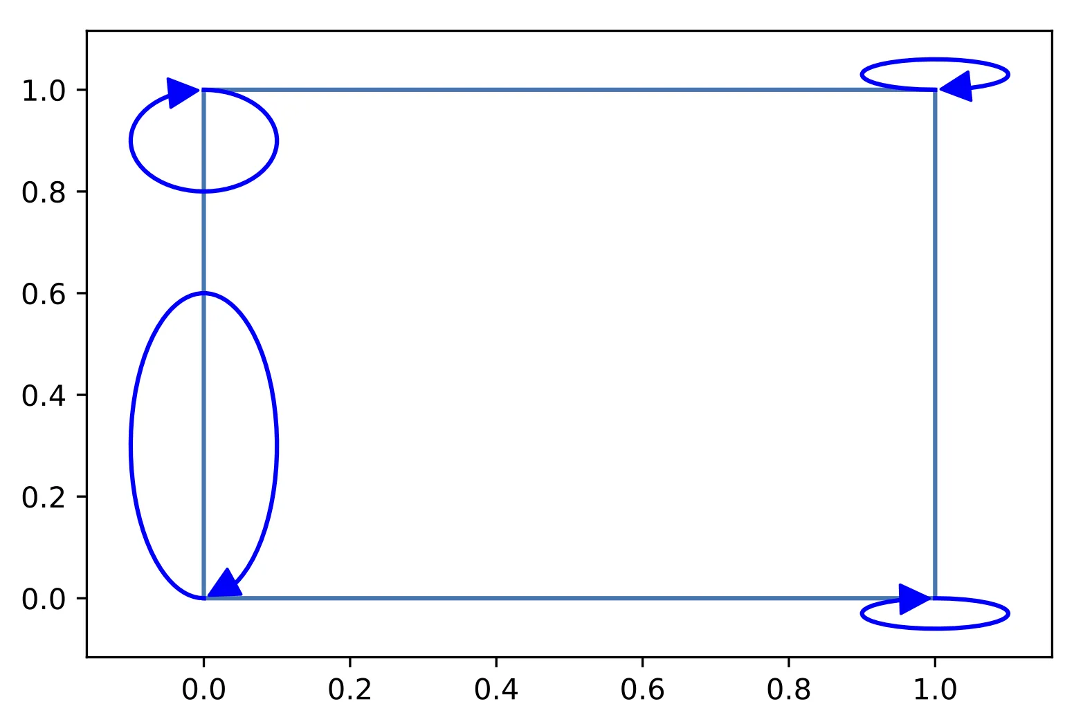
这并不能得出正确的结果:
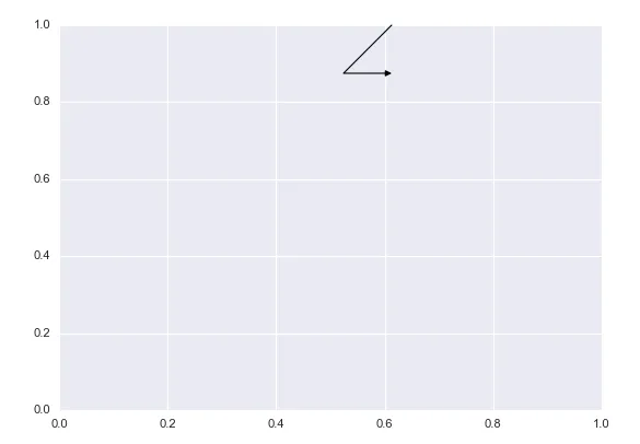
从这个页面(http://matplotlib.org/users/annotations_guide.html)上很难理解connectionstyle参数。

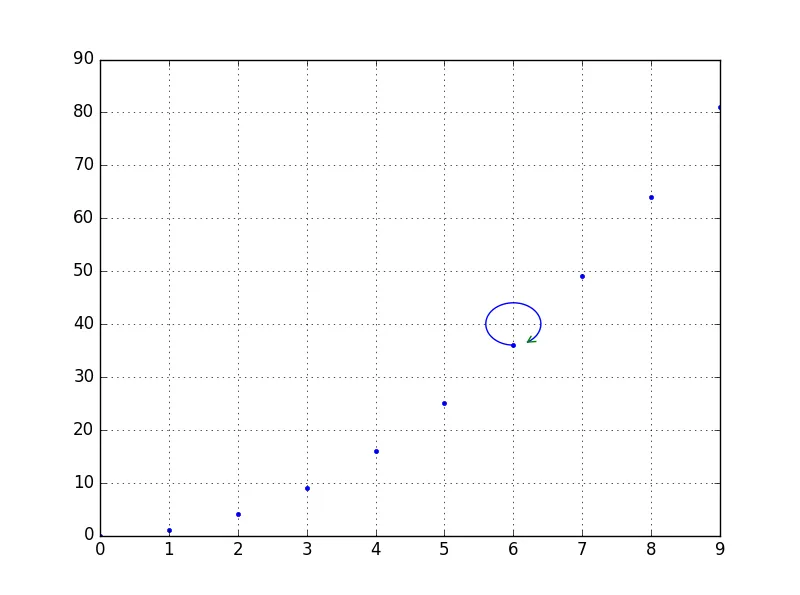
更新:所链接的答案没有展示如何在plt.annotate中实现此功能,而这个函数有其他我想要使用的特性。建议使用$\circlearrowleft$标记不是一个真正的解决方案。

