我有一个PATRICA trie,正在生成一个GraphViz文件。内部节点是跳过值,边缘是虚线0和实线1。最好将0放在1左边,给叶子节点一个字母顺序。我重新排列了访问图的顺序,所以
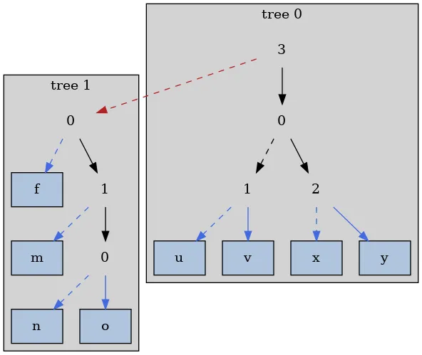
在一个图表上,它运行得很好,但子图的顺序与我想要的相反。
dot给出了这个结果。但是,当我使用子图将它们分组成森林时,我似乎无法强制dot可靠地尊重子图之间的边缘顺序。digraph {
rankdir=TB;
node [shape = box, style = filled, fillcolor = lightsteelblue];
// forest size 2.
subgraph cluster_tree0 {
style = filled; fillcolor = lightgray; label = "tree 0";
// branches
branch0_0 [label = "3", shape = none, fillcolor = none];
branch0_0 -> branch0_1;
branch0_1 [label = "0", shape = none, fillcolor = none];
branch0_1 -> branch0_2 [style = dashed];
branch0_2 [label = "1", shape = none, fillcolor = none];
branch0_2 -> leaf0_1 [style = dashed, color = royalblue];
branch0_2 -> leaf0_2 [color = royalblue];
branch0_1 -> branch0_3;
branch0_3 [label = "2", shape = none, fillcolor = none];
branch0_3 -> leaf0_3 [style = dashed, color = royalblue];
branch0_3 -> leaf0_4 [color = royalblue];
// leaves
leaf0_1 [label = "u"];
leaf0_2 [label = "v"];
leaf0_3 [label = "x"];
leaf0_4 [label = "y"];
}
branch0_0 -> branch1_0 [lhead = cluster_tree0, ltail = cluster_tree1, color = firebrick, style = dashed];
subgraph cluster_tree1 {
style = filled; fillcolor = lightgray; label = "tree 1";
// branches
branch1_0 [label = "0", shape = none, fillcolor = none];
branch1_0 -> leaf1_0 [style = dashed, color = royalblue];
branch1_0 -> branch1_1;
branch1_1 [label = "1", shape = none, fillcolor = none];
branch1_1 -> leaf1_1 [style = dashed, color = royalblue];
branch1_1 -> branch1_2;
branch1_2 [label = "0", shape = none, fillcolor = none];
branch1_2 -> leaf1_2 [style = dashed, color = royalblue];
branch1_2 -> leaf1_3 [color = royalblue];
// leaves
leaf1_0 [label = "f"];
leaf1_1 [label = "m"];
leaf1_2 [label = "n"];
leaf1_3 [label = "o"];
}
}
在一个图表上,它运行得很好,但子图的顺序与我想要的相反。
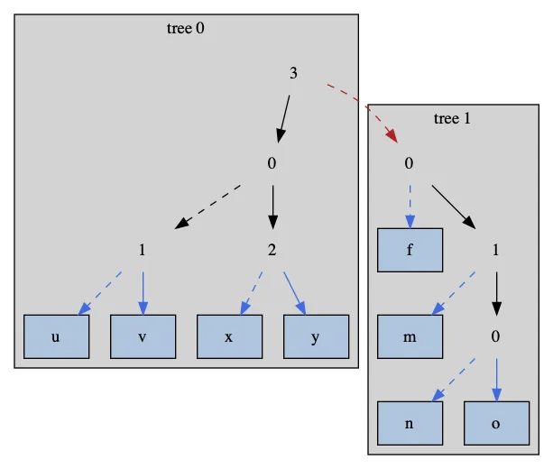
rank=same、ordering=out 和 invis 边缘来调整它,不知怎么搞的就把它翻转了,但我希望它是程序化的。有没有简单的方法将表示 0 的红色虚线画到实线表示 1 的左侧,而不是右侧?