我想在一个矩形对象中画一个渐变,给定一个角度(Theta),让渐变的两端触及矩形的周长。
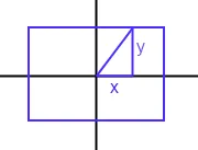
我认为使用正切函数会起作用,但是我无法消除其中的错误。有没有易于实现的算法?
最终结果
因此,这将是(angle, RectX1, RectX2, RectY1, RectY2)的一个函数。我希望以[x1, x2, y1, y2]的形式返回,以便渐变跨越整个正方形。 在我的问题中,如果原点为0,则x2=-x1且y2=-y1。但不总是在原点上。
我想在一个矩形对象中画一个渐变,给定一个角度(Theta),让渐变的两端触及矩形的周长。
我认为使用正切函数会起作用,但是我无法消除其中的错误。有没有易于实现的算法?
最终结果
因此,这将是(angle, RectX1, RectX2, RectY1, RectY2)的一个函数。我希望以[x1, x2, y1, y2]的形式返回,以便渐变跨越整个正方形。 在我的问题中,如果原点为0,则x2=-x1且y2=-y1。但不总是在原点上。
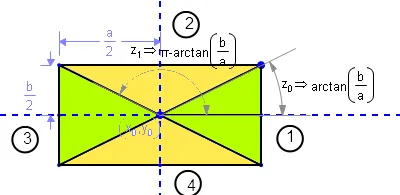
让我们称矩形的边为a和b,(x0,y0)是矩形中心的坐标。
您需要考虑四个区域:
    区域     起点            终点               位置
    ====================================================================
       1      -arctan(b/a)    +arctan(b/a)      右侧绿色三角形
       2      +arctan(b/a)    π-arctan(b/a)   上方黄色三角形
       3      π-arctan(b/a) π+arctan(b/a)   左侧绿色三角形
       4      π+arctan(b/a) -arctan(b/a)      下方黄色三角形
通过一些三角运算技巧,我们可以在每个区域中得出所需交点的坐标:
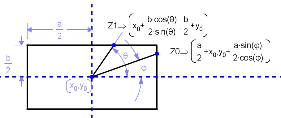
因此,当处于第1和第3区域时,Z0是交点的表达式。
当处于第2和第4区域时,Z1是交点的表达式。
所需的线从(X0,Y0)到Z0或Z1,具体取决于所处的区域。 因此,请记住Tan(φ)=Sin(φ)/Cos(φ):
    区域中的线段     起点                     终点
    ======================================================================
       1 和 3        (X0,Y0)      (X0 + a/2 , (a/2 * Tan(φ))+ Y0
       2 和 4        (X0,Y0)      (X0 + b/(2* Tan(φ)) , b/2 + Y0)
请注意每个象限中Tan(φ)的符号以及角度始终是从正X轴逆时针测量的。
希望对您有所帮助!
x(end)=X0 - a/2(请注意减号而非加号)。同样地,在区域4中,Y值的计算方式为Y(end)=Y0 - b/2。 - Felix Alcala好的,呼!,我终于搞定了。
注意:我是基于belisarius棒极了的答案进行的。如果你喜欢这个,也请点赞他的回答。我所做的只是把他说的话转化成代码。
下面是Objective-C的样子。将它转换为你最喜欢的语言应该很简单。
+ (CGPoint) edgeOfView: (UIView*) view atAngle: (float) theta
{
    // Move theta to range -M_PI .. M_PI
    const double twoPI = M_PI * 2.;
    while (theta < -M_PI)
    {
        theta += twoPI;
    }

    while (theta > M_PI)
    {
        theta -= twoPI;
    }

    // find edge ofview
    // Ref: https://dev59.com/Tm855IYBdhLWcg3w-JMr
    float aa = view.bounds.size.width;                                          // "a" in the diagram
    float bb = view.bounds.size.height;                                         // "b"

    // Find our region (diagram)
    float rectAtan = atan2f(bb, aa);
    float tanTheta = tan(theta);

    int region;
    if ((theta > -rectAtan)
    &&  (theta <= rectAtan) )
    {
        region = 1;
    }
    else if ((theta >  rectAtan)
    &&       (theta <= (M_PI - rectAtan)) )
    {
        region = 2;
    }
    else if ((theta >   (M_PI - rectAtan))
    ||       (theta <= -(M_PI - rectAtan)) )
    {
        region = 3;
    }
    else
    {
        region = 4;
    }

    CGPoint edgePoint = view.center;
    float xFactor = 1;
    float yFactor = 1;

    switch (region)
    {
        case 1: yFactor = -1;       break;
        case 2: yFactor = -1;       break;
        case 3: xFactor = -1;       break;
        case 4: xFactor = -1;       break;
    }

    if ((region == 1)
    ||  (region == 3) )
    {
        edgePoint.x += xFactor * (aa / 2.);                                     // "Z0"
        edgePoint.y += yFactor * (aa / 2.) * tanTheta;
    }
    else                                                                        // region 2 or 4
    {
        edgePoint.x += xFactor * (bb / (2. * tanTheta));                        // "Z1"
        edgePoint.y += yFactor * (bb /  2.);
    }

    return edgePoint;
}
此外,我创建了一个小的测试视图来验证其工作情况。创建此视图并将其放在某个地方,它将使另一个小视图在边缘周围移动。
@interface DebugEdgeView()
{
    int degrees;
    UIView *dotView;
    NSTimer *timer;
}

@end

@implementation DebugEdgeView

- (void) dealloc
{
    [timer invalidate];
}


- (id) initWithFrame: (CGRect) frame
{
    self = [super initWithFrame: frame];
    if (self)
    {
        self.backgroundColor = [[UIColor magentaColor] colorWithAlphaComponent: 0.25];
        degrees = 0;
        self.clipsToBounds = NO;

        // create subview dot
        CGRect dotRect = CGRectMake(frame.size.width / 2., frame.size.height / 2., 20, 20);
        dotView = [[DotView alloc] initWithFrame: dotRect];
        dotView.backgroundColor = [UIColor magentaColor];
        [self addSubview: dotView];

        // move it around our edges
        timer = [NSTimer scheduledTimerWithTimeInterval: (5. / 360.)
                                                 target: self
                                               selector: @selector(timerFired:)
                                               userInfo: nil
                                                repeats: YES];
    }

    return self;
}


- (void) timerFired: (NSTimer*) timer
{
    float radians = ++degrees * M_PI / 180.;
    if (degrees > 360)
    {
        degrees -= 360;
    }

    dispatch_async(dispatch_get_main_queue(), ^{
        CGPoint edgePoint = [MFUtils edgeOfView: self atAngle: radians];
        edgePoint.x += (self.bounds.size.width  / 2.) - self.center.x;
        edgePoint.y += (self.bounds.size.height / 2.) - self.center.y;
        dotView.center = edgePoint;
    });
}

@end
Javascript 版本:
function edgeOfView(rect, deg) {
  var twoPI = Math.PI*2;
  var theta = deg * Math.PI / 180;

  while (theta < -Math.PI) {
    theta += twoPI;
  }

  while (theta > Math.PI) {
    theta -= twoPI;
  }

  var rectAtan = Math.atan2(rect.height, rect.width);
  var tanTheta = Math.tan(theta);
  var region;

  if ((theta > -rectAtan) && (theta <= rectAtan)) {
      region = 1;
  } else if ((theta > rectAtan) && (theta <= (Math.PI - rectAtan))) {
      region = 2;
  } else if ((theta > (Math.PI - rectAtan)) || (theta <= -(Math.PI - rectAtan))) {
      region = 3;
  } else {
      region = 4;
  }

  var edgePoint = {x: rect.width/2, y: rect.height/2};
  var xFactor = 1;
  var yFactor = 1;

  switch (region) {
    case 1: yFactor = -1; break;
    case 2: yFactor = -1; break;
    case 3: xFactor = -1; break;
    case 4: xFactor = -1; break;
  }

  if ((region === 1) || (region === 3)) {
    edgePoint.x += xFactor * (rect.width / 2.);                                     // "Z0"
    edgePoint.y += yFactor * (rect.width / 2.) * tanTheta;
  } else {
    edgePoint.x += xFactor * (rect.height / (2. * tanTheta));                        // "Z1"
    edgePoint.y += yFactor * (rect.height /  2.);
  }

  return edgePoint;
};这个问题有一个很好的(更加编程化的iOS/Objective-C)答案,可以在Find the CGPoint on a UIView rectangle intersected by a straight line at a given angle from the center point找到,其中包括以下步骤:
虚幻引擎4(UE4)C++版本。
注意:这是基于Olie的代码。基于Belisarius的答案。如果这对你有帮助,请给这些人点赞。
更改:使用UE4语法和函数,并且角度被取反。
头文件
UFUNCTION(BlueprintCallable, meta = (DisplayName = "Project To Rectangle Edge (Radians)"), Category = "Math|Geometry")
static void ProjectToRectangleEdgeRadians(FVector2D Extents, float Angle, FVector2D & EdgeLocation);
代码
void UFunctionLibrary::ProjectToRectangleEdgeRadians(FVector2D Extents, float Angle, FVector2D & EdgeLocation)
{
    // Move theta to range -M_PI .. M_PI. Also negate the angle to work as expected.
    float theta = FMath::UnwindRadians(-Angle);

    // Ref: https://dev59.com/Tm855IYBdhLWcg3w-JMr
    float a = Extents.X; // "a" in the diagram | Width
    float b = Extents.Y; // "b"                | Height

    // Find our region (diagram)
    float rectAtan = FMath::Atan2(b, a);
    float tanTheta = FMath::Tan(theta);

    int region;
    if ((theta > -rectAtan) && (theta <= rectAtan))
    {
        region = 1;
    }
    else if ((theta > rectAtan) && (theta <= (PI - rectAtan)))
    {
        region = 2;
    }
    else if ((theta > (PI - rectAtan)) || (theta <= -(PI - rectAtan)))
    {
        region = 3;
    }
    else
    {
        region = 4;
    }

    float xFactor = 1.f;
    float yFactor = 1.f;

    switch (region)
    {
        case 1: yFactor = -1; break;
        case 2: yFactor = -1; break;
        case 3: xFactor = -1; break;
        case 4: xFactor = -1; break;
    }

    EdgeLocation = FVector2D(0.f, 0.f); // This rese is nessesary, UE might re-use otherwise.

    if (region == 1 || region == 3)
    {
        EdgeLocation.X += xFactor * (a / 2.f);              // "Z0"
        EdgeLocation.Y += yFactor * (a / 2.f) * tanTheta;
    }
    else // region 2 or 4
    {
        EdgeLocation.X += xFactor * (b / (2.f * tanTheta)); // "Z1"
        EdgeLocation.Y += yFactor * (b / 2.f);
    }
}
对于Java,LibGDX。我已经将角度设置为double类型以增加精度。
public static Vector2 projectToRectEdge(double angle, float width, float height, Vector2 out)
{
    return projectToRectEdgeRad(Math.toRadians(angle), width, height, out);
}

public static Vector2 projectToRectEdgeRad(double angle, float width, float height, Vector2 out)
{
    float theta = negMod((float)angle + MathUtils.PI, MathUtils.PI2) - MathUtils.PI;

    float diag = MathUtils.atan2(height, width);
    float tangent = (float)Math.tan(angle);

    if (theta > -diag && theta <= diag)
    {
        out.x = width / 2f;
        out.y = width / 2f * tangent;
    }
    else if(theta > diag && theta <= MathUtils.PI - diag)
    {
        out.x = height / 2f / tangent;
        out.y = height / 2f;
    }
    else if(theta > MathUtils.PI - diag && theta <= MathUtils.PI + diag)
    {
        out.x = -width / 2f;
        out.y = -width / 2f * tangent;
    }
    else
    {
        out.x = -height / 2f / tangent;
        out.y = -height / 2f;
    }

    return out;
}
PYTHON
import math
import matplotlib.pyplot as plt

twoPI = math.pi * 2.0
PI = math.pi

def get_points(width, height, theta):
    theta %= twoPI

    aa = width
    bb = height

    rectAtan = math.atan2(bb,aa)
    tanTheta = math.tan(theta)

    xFactor = 1
    yFactor = 1

    # determine regions
    if theta > twoPI-rectAtan or theta <= rectAtan:
        region = 1
    elif theta > rectAtan and theta <= PI-rectAtan:
        region = 2

    elif theta > PI - rectAtan and theta <= PI + rectAtan:
        region = 3
        xFactor = -1
        yFactor = -1
    elif theta > PI + rectAtan and theta < twoPI - rectAtan:
        region = 4
        xFactor = -1
        yFactor = -1
    else:
        print(f"region assign failed : {theta}")
        raise

    # print(region, xFactor, yFactor)
    edgePoint = [0,0]
    ## calculate points
    if (region == 1) or (region == 3):
        edgePoint[0] += xFactor * (aa / 2.)
        edgePoint[1] += yFactor * (aa / 2.) * tanTheta
    else:
        edgePoint[0] += xFactor * (bb / (2. * tanTheta))
        edgePoint[1] += yFactor * (bb /  2.)

    return region, edgePoint

l_x = []
l_y = []
theta = 0
for _ in range(10000):
    r, (x, y) = get_points(600,300, theta)
    l_x.append(x)
    l_y.append(y)
    theta += (0.01 / PI)

    if _ % 100 == 0:
        print(r, x,y)

plt.plot(l_x, l_y)
plt.show()
Unity C#(从Winter的Java代码转换而来)
    public Vector2 DetermineRectangleEdge(float aDegrees, float aWidth, float aHeight) {

        if (aDegrees < -90)
            aDegrees += 360f;

        float ANGLE = Mathf.Deg2Rad * aDegrees;
        float diag = Mathf.Atan2(aHeight, aWidth);
        float tangent = Mathf.Tan(ANGLE);

        Vector2 OUT = Vector2.zero;

        if (ANGLE > -diag && ANGLE <= diag)
        {
            OUT.x = aWidth / 2f;
            OUT.y = aWidth / 2f * tangent;
            _ObjectRectTransform.sizeDelta = _VerticalSize;
        }
        else if(ANGLE > diag && ANGLE <= Mathf.PI - diag)
        {
            OUT.x = aHeight / 2f / tangent;
            OUT.y = aHeight / 2f;
            _ObjectRectTransform.sizeDelta = _HorizontalSize;
        }
        else if(ANGLE > Mathf.PI - diag && ANGLE <= Mathf.PI + diag)
        {
            OUT.x = -aWidth / 2f;
            OUT.y = -aWidth / 2f * tangent;
            _ObjectRectTransform.sizeDelta = _VerticalSize;
        }
        else
        {
            OUT.x = -aHeight / 2f / tangent;
            OUT.y = -aHeight / 2f;
            _ObjectRectTransform.sizeDelta = _HorizontalSize;
        }

        return OUT;

    }