glLineStipple已经在最新的OpenGL API中被弃用。
它被什么替代了呢?
如果没有替代品,如何获得类似的效果?
(当然我不想使用兼容性配置文件...)
3个回答
31
抱歉,它还没有被替换为任何内容。模拟它的第一个想法是使用几何着色器。您将线提供给几何着色器,计算其屏幕空间长度,并根据此生成其起始和结束顶点之间数量可变的子线。
编辑:也许您还可以使用带有 alpha(或红色)通道编码图案的 1D 纹理,其中 0.0 表示无线,1.0 表示有线,然后使线条纹理坐标从 0 到 1,在片段着色器中进行简单的 alpha 测试,丢弃 alpha 低于某个阈值的片段。 您可以在几何着色器中为生成线条纹理坐标提供便利,否则您需要为每条线使用不同的顶点。通过这种方式,您还可以使纹理坐标取决于线的屏幕空间长度。
如果您绘制三角形(使用多边形模式 GL_LINE),则整个过程会更加困难。然后你必须在几何着色器中自己执行三角形-线转换,放入三角形并输出线条(这也可能是取消多边形模式的原因之一,如果它尚未被弃用)。
编辑:虽然我相信这个问题已经被放弃了,但我为第二种方法创建了一个简单的着色器三元组。这只是一个最小化的解决方案,您可以随意添加自定义功能。由于我缺乏必要的硬件,因此我没有测试它,但您应该能够理解:
uniform mat4 modelViewProj;

layout(location=0) in vec4 vertex;

void main()
{
    gl_Position = modelViewProj * vertex;
}
顶点着色器是一个简单的传递过程。
layout(lines) in;
layout(line_strip, max_vertices=2) out;

uniform vec2 screenSize;
uniform float patternSize;

noperspective out float texCoord;

void main()
{
    vec2 winPos0 = screenSize.xy * gl_in[0].gl_Position.xy / gl_in[0].gl_Position.w;
    vec2 winPos1 = screenSize.xy * gl_in[1].gl_Position.xy / gl_in[1].gl_Position.w;
    gl_Position = gl_in[0].gl_Position;
    texCoord = 0.0;
    EmitVertex();
    gl_Position = gl_in[1].gl_Position;
    texCoord = 0.5 * length(winPos1-winPos0) / patternSize;
    EmitVertex();
}
在几何着色器中,我们取一条线并计算其屏幕空间像素长度。然后将其除以点划线图案纹理的大小,当模拟对glLineStipple(factor, pattern)的调用时,这个大小将为factor*16。这被视为第二条线端点的1D纹理坐标。
请注意,必须线性插值这个纹理坐标(使用noperspective插值说明符)。通常的透视校正插值会导致在线的远离部分,点划线图案会被"挤在一起",而我们明确地使用屏幕空间值来进行计算。
uniform sampler1D pattern;
uniform vec4 lineColor;

noperspective in float texCoord;

layout(location=0) out vec4 color;

void main()
{
    if(texture(pattern, texCoord).r < 0.5)
        discard;
    color = lineColor;
}
GL_REPEAT,至于过滤模式,我不太确定,但我认为 GL_NEAREST 会是个好主意。
但正如之前所说,如果您想使用 glPolygonMode 渲染三角形,这种方法行不通。相反,您必须调整几何着色器以接受三角形并为每个三角形生成 3 条线。
编辑: 实际上,OpenGL 3 中着色器对整数操作的直接支持使我们完全可以放弃这种一维纹理的处理方式,直接使用实际位模式处理。因此,几何着色器略有改动,以输出实际屏幕大小的图案坐标,而不进行归一化:
texCoord = 0.5 * length(winPos1-winPos0);
 glLineStipple 的16位值相比为32位),并且以及图案的拉伸因子,然后取纹理坐标(实际上没有纹理了,但是不要紧)对32取模以获取它在图案上的位置(那些明确的 uint 很烦人,但我的GLSL编译器说 int 和 uint 之间的隐式转换是邪恶的):uniform uint pattern;
uniform float factor;

...
uint bit = uint(round(linePos/factor)) & 31U;
if((pattern & (1U<<bit)) == 0U)
    discard;
- Christian Rau
4
2太棒了。但在OpenGLES-2中能否不使用几何着色器完成? - Bram
@Bram 是的。我没有使用几何着色器来生成新的图元,只是为了计算基于屏幕空间长度的线条纹理坐标。你可以不用GS来做到这一点,但在这种情况下,你将不得不在CPU上计算texCoords。但这意味着你必须复制顶点,因为每个顶点需要不同的texCoord来绘制每条线,而你不能轻易地将其与屏幕空间大小相关联(好吧,你仍然可以在CPU上计算它的屏幕空间长度,但每帧都要这样做吗?)。它不能在VS中完成,因为你只能看到一个顶点而不是整条线。 - Christian Rau
@Bram 原理技术无非是在线条上进行简单的 alpha 映射(想象一下你最喜欢的游戏中的铁丝网或树叶)。它只是自动计算线条屏幕长度从而获得几何着色器的优势,但并不是因为它需要复杂的基元生成,而是因为 GS 是唯一能看到整个基元而不仅仅是单个顶点或片段的着色器。您可以使用线条的对象空间大小,这不依赖于变换并且可以预先计算。但这样做无法很好地模拟
glLineStipple。 - Christian Rau@ChristianRau,这是一个旧问题,但我想知道在CPU上如何计算纹理坐标,因为我对几何着色器遇到了很大麻烦,例如:
0(2):错误C3008:未知的布局说明符'lines'
0(3):错误C3008:未知的布局说明符'max_vertices'
0(3):错误C3008:未知的布局说明符'line_strip' - Veysel Bekir Macit
15
要回答这个问题,我们首先需要调查一下 glLineStipple 到底是做什么的。
看一下这幅图片,在左侧的正方形中使用了由 4 条分离线段绘制而成的基本类型 GL_LINES。
右侧的圆圈是通过连续的多边形线条绘制的,使用了基本类型 GL_LINE_STRIP。
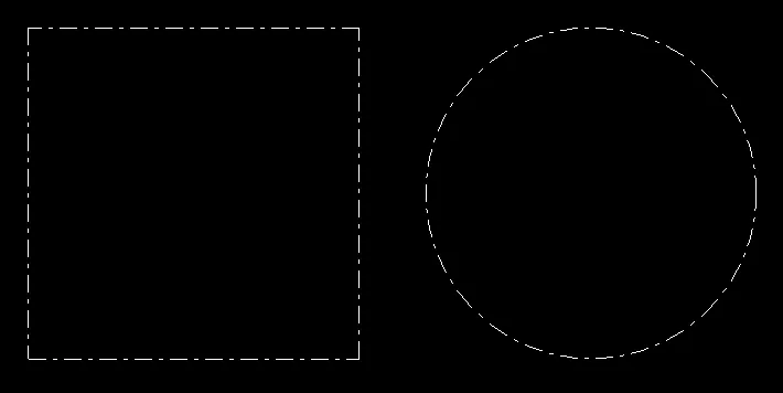
当使用线段时,每个线段都会从一个图案开始。该图案在每个基元处被重启。
当使用线条时,图案则无缝地应用于整个多边形。图案在顶点坐标之外平滑地延伸。
请注意,对角线上的长度会被拉伸。这可能是实现的关键。
对于单独的线段,这并不是很复杂,但对于线条来说,情况就变得有些复杂了。在着色器程序中无法计算出线的长度,而不知道线的所有基元。即使已知所有基元(例如 SSBO),则计算也必须在循环中完成。
也可以参见 使用 OpenGL 核心配置文件绘制虚线。
无论如何,实现几何着色器并不是必要的。关键是知道如何在片段着色器中找到线段的起始点。这可以通过使用 flat 插值限定符轻松实现。
顶点着色器必须将规范化设备坐标传递给片段着色器。一次使用默认插值,一次使用无插值 (flat) 插值。这导致在片段着色器中,第一个输入参数包含实际位置的 NDC 坐标,而后面的 NDC 坐标则是线的起始点。
#version 330

layout (location = 0) in vec3 inPos;

flat out vec3 startPos;
out vec3 vertPos;

uniform mat4 u_mvp;

void main()
{
    vec4 pos    = u_mvp * vec4(inPos, 1.0);
    gl_Position = pos;
    vertPos     = pos.xyz / pos.w;
    startPos    = vertPos;
}
另外,片元着色器还有统一变量,除了不同的输入,u_resolution 包含视口的宽度和高度。 u_factor 和 u_pattern 是乘数和16位模式,根据glLineStipple的参数而定。
因此,可以计算从起点到实际片元的线段长度:
vec2  dir  = (vertPos.xy-startPos.xy) * u_resolution/2.0;
float dist = length(dir);
使用 discard 命令可以丢弃片段的间隙。
uint bit = uint(round(dist / u_factor)) & 15U;
if ((u_pattern & (1U<<bit)) == 0U)
    discard;
片段着色器:
#version 330

flat in vec3 startPos;
in vec3 vertPos;

out vec4 fragColor;

uniform vec2  u_resolution;
uniform uint  u_pattern;
uniform float u_factor;

void main()
{
    vec2  dir  = (vertPos.xy-startPos.xy) * u_resolution/2.0;
    float dist = length(dir);

    uint bit = uint(round(dist / u_factor)) & 15U;
    if ((u_pattern & (1U<<bit)) == 0U)
        discard;
    fragColor = vec4(1.0);
}
使用这种实现比使用几何着色器更加简便和简短。自GLSL 1.30和GLSL ES 3.00开始支持flat插值限定符。在此版本中,不支持几何着色器。
请查看使用以上着色器生成的线条渲染。
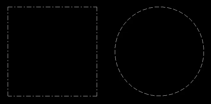
该着色器可以正确地生成线段结果,但无法针对线条进行处理,因为在每个顶点坐标上重新启动了点画样式。
即使使用几何着色器也无法解决此问题。此部分问题仍未得到解决。
对于以下简单的演示程序,我使用了GLFW API创建窗口,使用GLEW加载OpenGL,并使用GLM -OpenGL Mathematics进行数学运算。我不提供CreateProgram函数的代码,该函数只是从顶点着色器和片段着色器源代码创建程序对象:
#include <vector>
#include <string>
#include <glm/glm.hpp>
#include <glm/gtc/matrix_transform.hpp>
#include <glm/gtc/type_ptr.hpp>
#include <gl/gl_glew.h>
#include <GLFW/glfw3.h>

std::string vertShader = R"(
#version 330

layout (location = 0) in vec3 inPos;

flat out vec3 startPos;
out vec3 vertPos;

uniform mat4 u_mvp;

void main()
{
    vec4 pos    = u_mvp * vec4(inPos, 1.0);
    gl_Position = pos;
    vertPos     = pos.xyz / pos.w;
    startPos    = vertPos;
}
)";

std::string fragShader = R"(
#version 330

flat in vec3 startPos;
in vec3 vertPos;

out vec4 fragColor;

uniform vec2  u_resolution;
uniform uint  u_pattern;
uniform float u_factor;

void main()
{
    vec2  dir  = (vertPos.xy-startPos.xy) * u_resolution/2.0;
    float dist = length(dir);

    uint bit = uint(round(dist / u_factor)) & 15U;
    if ((u_pattern & (1U<<bit)) == 0U)
        discard;
    fragColor = vec4(1.0);
}
)";

GLuint CreateVAO(std::vector<glm::vec3> &varray)
{
    GLuint bo[2], vao;
    glGenBuffers(2, bo);
    glGenVertexArrays(1, &vao);
    glBindVertexArray(vao);
    glEnableVertexAttribArray(0);
    glBindBuffer(GL_ARRAY_BUFFER, bo[0] );
    glBufferData(GL_ARRAY_BUFFER, varray.size()*sizeof(*varray.data()), varray.data(), GL_STATIC_DRAW);
    glVertexAttribPointer(0, 3, GL_FLOAT, GL_FALSE, 0, 0);

    return vao;
}

int main(void)
{
    if ( glfwInit() == 0 )
        return 0;
    GLFWwindow *window = glfwCreateWindow( 800, 600, "GLFW OGL window", nullptr, nullptr );
    if ( window == nullptr )
        return 0;
    glfwMakeContextCurrent(window);

    glewExperimental = true;
    if ( glewInit() != GLEW_OK )
        return 0;

    GLuint program    = CreateProgram(vertShader, fragShader);
    GLint loc_mvp     = glGetUniformLocation(program, "u_mvp");
    GLint loc_res     = glGetUniformLocation(program, "u_resolution");
    GLint loc_pattern = glGetUniformLocation(program, "u_pattern");
    GLint loc_factor  = glGetUniformLocation(program, "u_factor");

    glUseProgram(program);

    GLushort pattern = 0x18ff;
    GLfloat  factor  = 2.0f;
    glUniform1ui(loc_pattern, pattern);
    glUniform1f(loc_factor, factor);
    //glLineStipple(2.0, pattern);
    //glEnable(GL_LINE_STIPPLE);

    glm::vec3 p0(-1.0f, -1.0f, 0.0f);
    glm::vec3 p1(1.0f, -1.0f, 0.0f);
    glm::vec3 p2(1.0f, 1.0f, 0.0f);
    glm::vec3 p3(-1.0f, 1.0f, 0.0f);
    std::vector<glm::vec3> varray1{ p0, p1, p1, p2, p2, p3, p3, p0 };
    GLuint vao1 = CreateVAO(varray1);

    std::vector<glm::vec3> varray2;
    for (size_t u=0; u <= 360; u += 8)
    {
        double a = u*M_PI/180.0;
        double c = cos(a), s = sin(a);
        varray2.emplace_back(glm::vec3((float)c, (float)s, 0.0f));
    }
    GLuint vao2 = CreateVAO(varray2);

    glm::mat4(project);
    int vpSize[2]{0, 0};
    while (!glfwWindowShouldClose(window))
    {
        int w, h;
        glfwGetFramebufferSize(window, &w, &h);
        if (w != vpSize[0] ||  h != vpSize[1])
        {
            vpSize[0] = w; vpSize[1] = h;
            glViewport(0, 0, vpSize[0], vpSize[1]);
            float aspect = (float)w/(float)h;
            project = glm::ortho(-aspect, aspect, -1.0f, 1.0f, -10.0f, 10.0f);
            glUniform2f(loc_res, (float)w, (float)h);
        }

        glClear(GL_COLOR_BUFFER_BIT);

        glm::mat4 modelview1( 1.0f );
        modelview1 = glm::translate(modelview1, glm::vec3(-0.6f, 0.0f, 0.0f) );
        modelview1 = glm::scale(modelview1, glm::vec3(0.5f, 0.5f, 1.0f) );
        glm::mat4 mvp1 = project * modelview1;

        glUniformMatrix4fv(loc_mvp, 1, GL_FALSE, glm::value_ptr(mvp1));
        glBindVertexArray(vao1);
        glDrawArrays(GL_LINES, 0, (GLsizei)varray1.size());

        glm::mat4 modelview2( 1.0f );
        modelview2 = glm::translate(modelview2, glm::vec3(0.6f, 0.0f, 0.0f) );
        modelview2 = glm::scale(modelview2, glm::vec3(0.5f, 0.5f, 1.0f) );
        glm::mat4 mvp2 = project * modelview2;

        glUniformMatrix4fv(loc_mvp, 1, GL_FALSE, glm::value_ptr(mvp2));
        glBindVertexArray(vao2);
        glDrawArrays(GL_LINE_STRIP, 0, (GLsizei)varray2.size());

        glfwSwapBuffers(window);
        glfwPollEvents();
    }
    glfwTerminate();

    return 0;
}
- Rabbid76
1
1哇,这真是个非常棒的主意,利用
flat属性和插值属性之间的差异!我之前还不知道glLineStipple实际上可以用于连续的条纹。 - undefined0
由于我曾经为了实现一组基于Christian Rau版本的点彩着色器而苦苦挣扎(无意冒犯),所以我认为如果我分享我的实现方式,对其他人可能会有用。
为了控制图案密度,片段着色器需要视口单位长度内的图案数量nPatterns,而不是设置一个因子。还包括一个可选的裁剪平面功能。
其余部分主要是注释和清理。
可自由使用于所有目的。
顶点着色器:
#version 330

in vec4 vertex;

void main(void)
{
    // just a pass-through
    gl_Position = vertex;
}
几何着色器:
#version 330

layout(lines) in;
layout(line_strip, max_vertices = 2) out;

uniform mat4 pvmMatrix;
uniform mat4 mMatrix;
uniform mat4 vMatrix;


out vec3 vPosition;  // passed to the fragment shader for plane clipping
out float texCoord;  // passed to the fragment shader for stipple pattern

void main(void)
{
    // to achieve uniform pattern density whatever the line orientation
    // the upper texture coordinate is made proportional to the line's length
    vec3 pos0 = gl_in[0].gl_Position.xyz;
    vec3 pos1 = gl_in[1].gl_Position.xyz;
    float max_u_texture = length(pos1 - pos0);

    // Line Start
    gl_Position = pvmMatrix * (gl_in[0].gl_Position);
    texCoord = 0.0;
    // depth position for clip plane
    vec4 vsPos0 = vMatrix * mMatrix * gl_Position;
    vPosition = vsPos0.xyz / vsPos0.w;
    EmitVertex();  // one down, one to go

    // Line End
    gl_Position = pvmMatrix * (gl_in[1].gl_Position);
    texCoord = max_u_texture;
    // depth position for clip plane
    vec4 vsPos1 = vMatrix * mMatrix * gl_Position;
    vPosition = vsPos0.xyz / vsPos0.w;
    EmitVertex();

    // done
    EndPrimitive();
}
片段着色器:
#version 330

uniform int pattern;   // an integer between 0 and 0xFFFF representing the bitwise pattern
uniform int nPatterns; // the number of patterns/unit length of the viewport, typically 200-300 for good pattern density
uniform vec4 color;
uniform vec4 clipPlane0; // defined in view-space

in float texCoord;

in vec3 vPosition;

layout(location=0) out vec4 fragColor;

void main(void)
{
    // test vertex postion vs. clip plane position (optional)
    if (vPosition.z > clipPlane0.w) {
        discard;
        return;
    }

    // use 4 bytes for the masking pattern
    // map the texture coordinate to the interval [0,2*8[
    uint bitpos = uint(round(texCoord * nPatterns)) % 16U;
    // move a unit bit 1U to position bitpos so that
    // bit is an integer between 1 and 1000 0000 0000 0000 = 0x8000
    uint bit = (1U << bitpos);

    // test the bit against the masking pattern
    //  Line::SOLID:       pattern = 0xFFFF;  // = 1111 1111 1111 1111 = solid pattern
    //  Line::DASH:        pattern = 0x3F3F;  // = 0011 1111 0011 1111
    //  Line::DOT:         pattern = 0x6666;  // = 0110 0110 0110 0110
    //  Line::DASHDOT:     pattern = 0xFF18;  // = 1111 1111 0001 1000
    //  Line::DASHDOTDOT:  pattern = 0x7E66;  // = 0111 1110 0110 0110
    uint up = uint(pattern);

    // discard the bit if it doesn't match the masking pattern
    if ((up & bit) == 0U) discard;

    fragColor = color;
}
- techwinder
网页内容由stack overflow 提供, 点击上面的可以查看英文原文,
原文链接
原文链接
- 相关问题
- 5 glBindBufferRange()在OpenGL 3.1中出现问题
- 22 为什么在OpenGL 3.1中弃用了显示列表?
- 3 OpenGL vs OpenGL ES以及OpenGL 1.x vs OpenGL 2.0要学习哪个?(涉及IT技术)
- 3 如何在OpenGL 3.1中使用glPixelTransfer、glTexEnv和glRasterPos?
- 3 OpenGL - OpenGL 3.1中的采样器是什么?
- 4 不使用废弃功能的CUDA + OpenGL互操作
- 5 OpenGl alpha test - 如何替代已废弃的AlphaFunc?
- 10 OpenGL 或 OpenGL ES
- 4 为什么在OpenGL 3.2及以上版本中GL_FRONT和GL_BACK已被弃用?
- 10 在没有使用OpenGL的情况下复制OpenGL正交投影行为