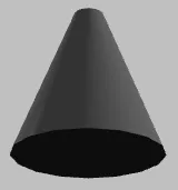
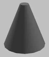
我这样创建Qt3D网格:
创建的网格看起来像这样:
在代码的后面,我尝试以 STL 二进制格式 导出上述网格。为此,我提取实体的几何和变换组件:
然后我获取包含顶点位置和法线的缓冲数据:
现在,我们专注于顶点位置属性和顶点法向量属性。我们获取每个属性的字节偏移量和字节步长,同时检查它们是否使用相同的数据缓冲区:
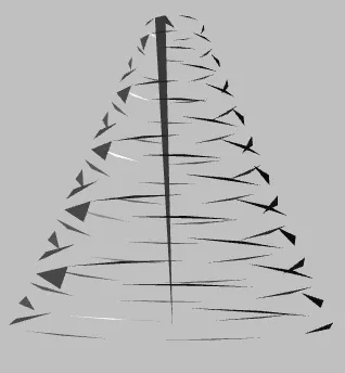
然后我使用字节偏移和字节跨度来提取三角形并将其写入STL文件。然而,导出的STL文件不好:
以上代码适用于自定义网格。我的意思是,当我将STL文件导入到我的Qt3D应用程序中,然后再将其导出为STL时,导出的STL是好的。问题在于:当创建Qt3D预制网格(如QConeMesh)时,导出的STL会出现问题,我是说整体几何图形没问题,但三角形混乱如上图所示。
当尝试导出QConeMesh时,我的代码记录以下值。可以看到,法向量具有单位大小,这表明它们实际上是法向量。
Qt3DCore::QEntity *newEntity = new Qt3DCore::QEntity();
Qt3DExtras::QConeMesh *mesh =new Qt3DExtras::QConeMesh();
mesh->setTopRadius(0.2);
mesh->setBottomRadius(1.0);
mesh->setLength(2.0);
for(int i = 0; i < mesh->geometry()->attributes().size(); ++i) {
    mesh->geometry()->attributes().at(i)->buffer()->setSyncData(true); // To have access to data
}
newEntity->addComponent(mesh);
创建的网格看起来像这样:
在代码的后面,我尝试以 STL 二进制格式 导出上述网格。为此,我提取实体的几何和变换组件:
Qt3DCore::QComponent *compoMesh = nullptr; // place holder for mesh geometry of entity
Qt3DCore::QComponent *compoTran = nullptr; // place holder for mesh transformation of entity
QVector<Qt3DCore::QComponent *> compos = newEntity->components();
for(int i = 0; i < compos.size(); ++i) {
    if (qobject_cast<Qt3DRender::QGeometryRenderer *>(compos.at(i))) {
        compoMesh = compos.at(i); // mesh geometry component
    } else if (qobject_cast<Qt3DCore::QTransform *>(compos.at(i))) {
        compoTran = compos.at(i); // mesh transformation component
    }
}
然后我获取包含顶点位置和法线的缓冲数据:
Qt3DRender::QGeometryRenderer *mesh = qobject_cast<Qt3DRender::QGeometryRenderer *>(compoMesh);
Qt3DRender::QGeometry *geometry = mesh->geometry();
QVector<Qt3DRender::QAttribute *> atts = geometry->attributes();
现在,我们专注于顶点位置属性和顶点法向量属性。我们获取每个属性的字节偏移量和字节步长,同时检查它们是否使用相同的数据缓冲区:
for(int i = 0; i < atts.size(); ++i) {
        if(atts.at(i)->name() == Qt3DRender::QAttribute::defaultPositionAttributeName()) {
            byteOffsetPos = atts.at(i)->byteOffset();
            byteStridePos = atts.at(i)->byteStride();
            bufferPtrPos = atts.at(i)->buffer();
        } else if(atts.at(i)->name() == Qt3DRender::QAttribute::defaultNormalAttributeName()) {
            byteOffsetNorm = atts.at(i)->byteOffset();
            byteStrideNorm = atts.at(i)->byteStride();
            bufferPtrNorm = atts.at(i)->buffer();
        }
    }
if(bufferPtrPos != bufferPtrNorm) {
    qDebug() << __func__ << "!!! Buffer pointer for position and normal are NOT the same";
    // Throw error here
    }
然后我使用字节偏移和字节跨度来提取三角形并将其写入STL文件。然而,导出的STL文件不好:
我使用相同的代码导出自定义网格的STL文件,这个过程很顺利。然而,当我使用相同的代码来导出Qt3D预制网格,如QConeMesh时,导出的STL文件是不可接受的。有人能给我一些提示吗?
更新
如 @vre 所指出的,我将发布编写三角形到STL文件的其余代码。这是一段较长的代码,我尽力保持其清晰简洁:
为了获取三角形位置和法线,我循环遍历属性并获取存储所有位置和法线的 VertexBuffer 缓冲区:
// I loop over attributes to get access to VertexBuffer buffer
for(int i = 0; i < atts.size(); ++i) {
    Qt3DRender::QBuffer *buffer = atts.at(i)->buffer();
    QByteArray data = buffer->data();
    // We focus on VertexBuffer, NOT IndexBuffer!
    if( buffer->type() == Qt3DRender::QBuffer::VertexBuffer ) {
        // Number of triangles is number of vertices divided by 3:
        quint32 trianglesCount = atts.at(i)->count() / 3;

        // For each triangle, extract vertex positions and normals
        for(int j = 0; j < trianglesCount; ++j) {
            // Index for each triangle positions data
            // Each triangle has 3 vertices, hence 3 factor:
            // We already know byte-offset and byte-stride for positions
            int idxPos  = byteOffsetPos  + j * 3 * byteStridePos ;
            // Index for each triangle normals data
            // Each tirangle has 3 normals (right?), hence 3 factor:
            // We already know byte-offset and byte-stride for normals
            int idxNorm = byteOffsetNorm + j * 3 * byteStrideNorm;

            // Get x, y, z positions for 1st vertex
            // I have already checked that attribute base type is float by: `atts.at(i)->vertexBaseType();`
            QByteArray pos0x = data.mid(idxPos + 0 * sizeof(float), sizeof(float));
            QByteArray pos0y = data.mid(idxPos + 1 * sizeof(float), sizeof(float));
            QByteArray pos0z = data.mid(idxPos + 2 * sizeof(float), sizeof(float));

            // Get x, y z for 1st normal
            QByteArray norm0x= data.mid(idxNorm + 0 * sizeof(float), sizeof(float));
            QByteArray norm0y= data.mid(idxNorm + 1 * sizeof(float), sizeof(float));
            QByteArray norm0z= data.mid(idxNorm + 2 * sizeof(float), sizeof(float));

            // Get x, y, z positions for 2nd vertex
            QByteArray pos1x = data.mid(idxPos  + 1 * byteStridePos + 0 * sizeof(float), sizeof(float));
            QByteArray pos1y = data.mid(idxPos  + 1 * byteStridePos + 1 * sizeof(float), sizeof(float));
            QByteArray pos1z = data.mid(idxPos  + 1 * byteStridePos + 2 * sizeof(float), sizeof(float));

            // Get x, y, z for 2nd normal
            QByteArray norm1x= data.mid(idxNorm + 1 * byteStrideNorm + 0 * sizeof(float), sizeof(float));
            QByteArray norm1y= data.mid(idxNorm + 1 * byteStrideNorm + 1 * sizeof(float), sizeof(float));
            QByteArray norm1z= data.mid(idxNorm + 1 * byteStrideNorm + 2 * sizeof(float), sizeof(float));

            // Get x, y, z positions for 3rd vertex
            QByteArray pos2x = data.mid(idxPos  + 2 * byteStridePos + 0 * sizeof(float), sizeof(float));
            QByteArray pos2y = data.mid(idxPos  + 2 * byteStridePos + 1 * sizeof(float), sizeof(float));
            QByteArray pos2z = data.mid(idxPos  + 2 * byteStridePos + 2 * sizeof(float), sizeof(float));

            // Get x, y, z for 3rd normal
            QByteArray norm2x= data.mid(idxNorm + 2 * byteStrideNorm+ 0 * sizeof(float), sizeof(float));
            QByteArray norm2y= data.mid(idxNorm + 2 * byteStrideNorm+ 1 * sizeof(float), sizeof(float));
            QByteArray norm2z= data.mid(idxNorm + 2 * byteStrideNorm+ 2 * sizeof(float), sizeof(float));

            // Convert x, y, z byte arrays into floats
            float floatPos0x;
            if ( pos0x.size() >= sizeof(floatPos0x) ) {
                floatPos0x = *reinterpret_cast<const float *>( pos0x.data() );
            }
            float floatPos0y;
            if ( pos0y.size() >= sizeof(floatPos0y) ) {
                floatPos0y = *reinterpret_cast<const float *>( pos0y.data() );
            }
            float floatPos0z;
            if ( pos0z.size() >= sizeof(floatPos0z) ) {
                floatPos0z = *reinterpret_cast<const float *>( pos0z.data() );
            }

            // Do the rest of byte-array to float conversions:
            // norm0x=>floatNorm0x, norm0y=>floatNorm0y, norm0z=>floatNorm0z
            // pos1x=>floatPos1x, pos1y=>floatPos1y, pos1z=>floatPos1z
            // norm1x=>floatNorm1x, norm1y=>floatNorm1y, norm1z=>floatNorm1z
            // pos2x=>floatPos2x, pos2y=>floatPos2y, pos2z=>floatPos2z
            // norm2x=>floatNorm2x, norm2y=>floatNorm2y, norm2z=>floatNorm2z

            // Compose positions matrix before applying transformations
            // I'm going to use `QMatrix4x4` but I have 3 vertices of 3x1
            // Therefore I have to fill out `QMatrix4x4` with zeros and ones
            // Please see this question and its answer: https://stackoverflow.com/q/51979168/3405291
            QMatrix4x4 floatPos4x4 = QMatrix4x4(
                floatPos0x, floatPos1x, floatPos2x, 0,
                floatPos0y, floatPos1y, floatPos2y, 0,
                floatPos0z, floatPos1z, floatPos2z, 0,
                1         , 1         , 1         , 0
            );

            // Apply transformations to positions:
            // We already have transformations component `compoTran` from previous code:
            Qt3DCore::QTransform *tran = qobject_cast<Qt3DCore::QTransform *>(compoTran);
            QMatrix4x4 newFloatPos4x4 = tran->matrix() * floatPos4x4;

            // Get new positions after applying transformations:
            float newFloatPos0x = newFloatPos4x4(0,0);
            float newFloatPos0y = newFloatPos4x4(1,0);
            float newFloatPos0z = newFloatPos4x4(2,0);

            float newFloatPos1x = newFloatPos4x4(0,1);
            float newFloatPos1y = newFloatPos4x4(1,1);
            float newFloatPos1z = newFloatPos4x4(2,1);

            float newFloatPos2x = newFloatPos4x4(0,2);
            float newFloatPos2y = newFloatPos4x4(1,2);
            float newFloatPos2z = newFloatPos4x4(2,2);

            // Convert all the floats (after applying transformations) back to byte array:
            QByteArray newPos0x( reinterpret_cast<const char *>( &newFloatPos0x ), sizeof( newFloatPos0x ) );
            QByteArray newPos0y( reinterpret_cast<const char *>( &newFloatPos0y ), sizeof( newFloatPos0y ) );
            QByteArray newPos0z( reinterpret_cast<const char *>( &newFloatPos0z ), sizeof( newFloatPos0z ) );

            QByteArray newPos1x( reinterpret_cast<const char *>( &newFloatPos1x ), sizeof( newFloatPos1x ) );
            QByteArray newPos1y( reinterpret_cast<const char *>( &newFloatPos1y ), sizeof( newFloatPos1y ) );
            QByteArray newPos1z( reinterpret_cast<const char *>( &newFloatPos1z ), sizeof( newFloatPos1z ) );

            QByteArray newPos2x( reinterpret_cast<const char *>( &newFloatPos2x ), sizeof( newFloatPos2x ) );
            QByteArray newPos2y( reinterpret_cast<const char *>( &newFloatPos2y ), sizeof( newFloatPos2y ) );
            QByteArray newPos2z( reinterpret_cast<const char *>( &newFloatPos2z ), sizeof( newFloatPos2z ) );

            // Log triangle vertex positions and normals (float numbers)
            // A sample log is posted on this question on StackOverflow
            qDebug() << __func__ << " pos 0: x " << newFloatPos0x << " y " << newFloatPos0y << " z " << newFloatPos0z;
            qDebug() << __func__ << " pos 1: x " << newFloatPos1x << " y " << newFloatPos1y << " z " << newFloatPos1z;
            qDebug() << __func__ << " pos 2: x " << newFloatPos2x << " y " << newFloatPos2y << " z " << newFloatPos2z;

            qDebug() << __func__ << " norm 0: x " << floatNorm0x << " y " << floatNorm0y << " z " << floatNorm0z;
            qDebug() << __func__ << " norm 1: x " << floatNorm1x << " y " << floatNorm1y << " z " << floatNorm1z;
            qDebug() << __func__ << " norm 2: x " << floatNorm2x << " y " << floatNorm2y << " z " << floatNorm2z;

            // Write the triangle to STL file
            // Note that STL file needs a header which is written in another section of code
            // Note that STL file needs total number of triangles which is written in another section of code
            // Note that STL file needs only one normal vector for each triangle, but here we have 3 normals (for 3 vertices), therefore I'm writing only the 1st normal to STL (is it OK?!)
            // `baStl` is a byte-array containing all the STL data
            // `baStl` byte-array is written to a file in another section of the code
            QBuffer tempBuffer(&baStl);
            tempBuffer.open(QIODevice::Append);
            tempBuffer.write( norm0x   ); // vertex 0 Normal vector
            tempBuffer.write( norm0y   );
            tempBuffer.write( norm0z   );
            tempBuffer.write( newPos0x ); // New vertex 0 position
            tempBuffer.write( newPos0y );
            tempBuffer.write( newPos0z );
            tempBuffer.write( newPos1x ); // New vertex 1 position
            tempBuffer.write( newPos1y );
            tempBuffer.write( newPos1z );
            tempBuffer.write( newPos2x ); // New vertex 2 position
            tempBuffer.write( newPos2y );
            tempBuffer.write( newPos2z );
            tempBuffer.write("aa"); // Attribute byte count: UINT16: 2 bytes: content doesn't matter, just write 2 bytes
            tempBuffer.close();
        }
    }
}
以上代码适用于自定义网格。我的意思是,当我将STL文件导入到我的Qt3D应用程序中,然后再将其导出为STL时,导出的STL是好的。问题在于:当创建Qt3D预制网格(如QConeMesh)时,导出的STL会出现问题,我是说整体几何图形没问题,但三角形混乱如上图所示。
当尝试导出QConeMesh时,我的代码记录以下值。可以看到,法向量具有单位大小,这表明它们实际上是法向量。
...
exportStlUtil  pos 0: x  -10.6902  y  -7.55854  z  4.76837e-07
exportStlUtil  pos 1: x  -12.8579  y  -4.31431  z  2.98023e-07
exportStlUtil  pos 2: x  -13.6191  y  -0.487476  z  5.96046e-08
exportStlUtil  norm 0: x  -0.707107  y  0  z  0.707107
exportStlUtil  norm 1: x  -0.92388  y  0  z  0.382683
exportStlUtil  norm 2: x  -1  y  0  z  -8.74228e-08
exportStlUtil  pos 0: x  -12.8579  y  3.33936  z  -1.19209e-07
exportStlUtil  pos 1: x  -10.6902  y  6.58359  z  -3.57628e-07
exportStlUtil  pos 2: x  -7.44594  y  8.75132  z  -4.76837e-07
exportStlUtil  norm 0: x  -0.92388  y  0  z  -0.382683
exportStlUtil  norm 1: x  -0.707107  y  0  z  -0.707107
exportStlUtil  norm 2: x  -0.382683  y  0  z  -0.92388
exportStlUtil  pos 0: x  -3.61911  y  9.51252  z  -4.76837e-07
exportStlUtil  pos 1: x  0.207723  y  8.75132  z  -4.76837e-07
exportStlUtil  pos 2: x  3.45196  y  6.58359  z  -3.57628e-07
exportStlUtil  norm 0: x  1.19249e-08  y  0  z  -1
exportStlUtil  norm 1: x  0.382684  y  0  z  -0.923879
exportStlUtil  norm 2: x  0.707107  y  0  z  -0.707107
exportStlUtil  pos 0: x  5.61968  y  3.33936  z  -1.19209e-07
exportStlUtil  pos 1: x  6.38089  y  -0.487479  z  5.96046e-08
exportStlUtil  pos 2: x  6.38089  y  -0.487477  z  0.133333
exportStlUtil  norm 0: x  0.92388  y  0  z  -0.382683
exportStlUtil  norm 1: x  1  y  0  z  1.74846e-07
exportStlUtil  norm 2: x  1  y  0  z  0
exportStlUtil  pos 0: x  5.61968  y  -4.31431  z  0.133334
exportStlUtil  pos 1: x  3.45195  y  -7.55854  z  0.133334
exportStlUtil  pos 2: x  0.207721  y  -9.72627  z  0.133334
exportStlUtil  norm 0: x  0.92388  y  0  z  0.382683
exportStlUtil  norm 1: x  0.707107  y  0  z  0.707107
exportStlUtil  norm 2: x  0.382683  y  0  z  0.92388
...