长话短说
Android SDK中没有默认的减法颜色混合功能,但是您仍然可以通过使用OpenGL渲染API来实现。 这里 您可以找到这种解决方案的实现,封装在BlendingFilterUtil类中,可以像这样使用:
BlendingFilterUtil.subtractMatrixColorFilter(bitmap, new float[]{
    0.393f, 0.7689999f, 0.18899999f, 0, 0,
    0.349f, 0.6859999f, 0.16799999f, 0, 0,
    0.272f, 0.5339999f, 0.13099999f, 0, 0,
    0,      0,          0,           1, 0
}, activity, callback);
理论
首先,“在减去混合模式下使用颜色过滤器”是一个非常模糊的要求。为了更好地理解问题,让我们定义 Android 中的两个不同的功能集:颜色混合和颜色过滤。
颜色混合
颜色混合对于设计师和从事计算机图形工作的人来说是一件司空见惯的事情。它通常意味着使用通道值(称为红色、绿色、蓝色和 Alpha)和混合函数混合两种颜色。混合函数被称为混合模式,其中一种模式称为减去。减去混合模式使用以下公式得到其最终颜色:

其中Cout是结果颜色,Cdst是“当前”颜色,Csrc是用于改变原始颜色的颜色值。如果任何通道的差异为负,则使用0值。粗略地说,使用此模式可以使目标颜色比原始颜色更暗,因为通道由于函数的结果而接近零。在这里您可以找到一个非常生动的示例:
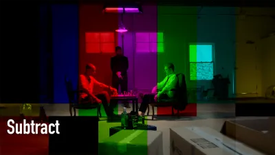
目标

源代码
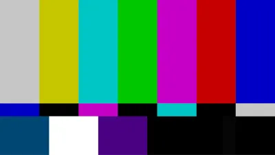
颜色混合输出
颜色过滤
在Android SDK的上下文中,颜色过滤是一组操作的超集,其中包括了颜色混合函数。ColorFilter子类的参考提供了SDK中可用颜色过滤选项的详细信息:
4x5 matrix for transforming the color and alpha components of a
Bitmap. The matrix can be passed as single array, and is treated as
follows:
[ a, b, c, d, e,
  f, g, h, i, j,
  k, l, m, n, o,
  p, q, r, s, t ]
When applied to a color [R, G, B, A], the resulting color is computed as:
R’ = a*R + b*G + c*B + d*A + e;
G’ = f*R + g*G + h*B + i*A + j;
B’ = k*R + l*G + m*B + n*A + o;
A’ = p*R + q*G + r*B + s*A + t;
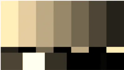
定义问题
现在我们知道,在Android SDK中,唯一使用ColorMatrix进行过滤操作的是ColorMatrixColorFilter。然而,它与颜色混合无关,因为颜色混合是两种颜色混合的结果,而ColorMatrixColorFilter只是修改输入颜色。下面是使用问题中矩阵过滤的示例图像的效果:
我能想到的唯一将这两个概念结合起来的方法是将ColorMatrixColorFilter的结果作为减法混合函数(Csrc)的参数使用,因此我们最终得到以下实现公式:

实现方法
这个任务并不需要什么花哨的东西:我们可以使用 ColorMatrixColorFilter,然后使用后续的 PorterDuffColorFilter 以减法模式进行过滤,使用过滤结果作为源颜色。然而,如果你仔细查看 PorterDuff.Mode 的参考文献,你会注意到Android没有减法混合模式在其设施中(Android操作系统在画布绘制方面使用Google的Skia库,在某些情况下确实缺乏减法模式),因此我们将不得不用另一种方式进行减法运算。
在 Open GL 渲染 API 中,这样的事情相对简单,但它需要我们处理设置 Open GL 上下文的挑战,以便让我们以所需的方式绘制我们需要的内容。
解决方案
Android已经有了GLSurfaceView,它在幕后设置了Open GL上下文,但必须在视图层次结构中才能实际执行任何渲染操作。我的计划是实例化一个GLSurfaceView,将其附加到应用程序窗口,给它一张我们想要应用效果的图片,并在幕后执行所有花哨的操作。之后,我们可以获取结果图像并静默地移除该视图。
添加GLSurfaceView
首先,实例化一个GLSurfaceView,设置OpenGL API版本和上下文配置:
GLSurfaceView hostView = new GLSurfaceView(activityContext);
hostView.setEGLContextClientVersion(2);
hostView.setEGLConfigChooser(8, 8, 8, 8, 0, 0);
现在必须将视图添加到视图层次结构中:
final WindowManager.LayoutParams layoutParams = new WindowManager.LayoutParams(width, height, TYPE_APPLICATION, 0, PixelFormat.OPAQUE);
view.setLayoutParams(layoutParams);
final WindowManager windowManager = (WindowManager) view.getContext().getSystemService(Context.WINDOW_SERVICE);
Objects.requireNonNull(windowManager).addView(view, layoutParams);
我将它放入根窗口,以便从应用程序中的任何活动中使用。布局的width和height参数应该与Bitmap的width和height匹配,这样生成的图像就不会出现不同的大小。
添加渲染器
GLSurfaceView本身不绘制任何内容。这项工作需要由Renderer完成。以下是给定问题的接口的初始实现:
class BlendingFilterRenderer implements GLSurfaceView.Renderer {
private final Bitmap mBitmap;
private final WeakReference<GLSurfaceView> mHostViewReference;
private final float[] mColorFilter;
private final BlendingFilterUtil.Callback mCallback;
private boolean mFinished = false;
BlendingFilterRenderer(@NonNull GLSurfaceView hostView, @NonNull Bitmap bitmap,
@NonNull float[] colorFilter,
@NonNull BlendingFilterUtil.Callback callback) throws IllegalArgumentException {
if (colorFilter.length != 4 * 5) {
throw new IllegalArgumentException("Color filter should be a 4 x 5 matrix");
}
mBitmap = bitmap;
mHostViewReference = new WeakReference<>(hostView);
mColorFilter = colorFilter;
mCallback = callback;
}
@Override
public void onSurfaceCreated(GL10 gl, EGLConfig config) {}
@Override
public void onSurfaceChanged(GL10 gl, int width, int height) {}
@Override
public void onDrawFrame(GL10 gl) {}
}
mBitmap - 因为渲染操作在单独的线程中进行,渲染器必须保留 Bitmap 参数,直到OpenGL上下文就绪。mHostViewReference - 需要一个弱引用来引用视图对象,以便在完成工作时从窗口中删除该视图。mColorFilter - 在此实现中不真正需要ColorMatrix对象,因此我使用普通的float[] Java数组来表示颜色矩阵。mCallback - 结果将通过回调传递,定义如下:
interface Callback {
    void onSuccess(@NonNull Bitmap blendedImage);
    void onFailure(@Nullable Exception error);
}
mFinished - 我不确定为什么,但在与Renderer对象玩耍时,我发现它执行了冗余的渲染循环。这会阻止程序在不再需要时执行任何操作。我还建议将GLSurfaceView对象的渲染模式设置为RENDERMODE_WHEN_DIRTY,以防止每秒60次的绘图:
hostView.setRenderer(new BlendingFilterRenderer(hostView, image, filterValues, callback));
hostView.setRenderMode(GLSurfaceView.RENDERMODE_WHEN_DIRTY);
绘制网格
为了在OpenGL中绘制像素,首先需要准备一些表面。为了绘制图像和构建画布(绘制表面),我们必须引入一些着色器程序(在OpenGL术语中是顶点和片段着色器)。通过对OpenGL API的调用,编译和加载着色器,并且首先需要定义一个方法,该方法接受着色器源代码,将其编译并检查是否无误(在 BlendingFilterRenderer 类内):
private int loadShader(int type, String shaderCode) throws GLException {
    int reference = GLES20.glCreateShader(type);
    GLES20.glShaderSource(reference, shaderCode);
    GLES20.glCompileShader(reference);
    int[] compileStatus = new int[1];
    GLES20.glGetShaderiv(reference, GLES20.GL_COMPILE_STATUS, compileStatus, 0);
    if (compileStatus[0] != GLES20.GL_TRUE) {
        GLES20.glDeleteShader(reference);
        final String message = GLES20.glGetShaderInfoLog(reference);
        throw new GLException(compileStatus[0], message);
    }

    return reference;
}
该方法的第一个参数定义了着色器类型(顶点或片元),第二个参数包含实际的着色器代码,作为String传入。让我们从非常简单的顶点着色器开始,它只需取一个顶点坐标(以归一化的二维向量给出)并将它们注入到变量gl_Position中(实质上是着色器的结果值):
attribute vec2 aPosition;
void main() {
    gl_Position = vec4(aPosition.x, aPosition.y, 0.0, 1.0);
}
目前,片段着色器的实现仅输出白色而没有任何更改:
precision mediump float;
void main() {
    gl_FragColor = vec4(1.0, 1.0, 1.0, 1.0);
}
OpenGL ES 2要求我们明确指定浮点精度,否则该程序将无法编译。此着色器还写入全局变量gl_FragColor,定义输出颜色。
通过之前定义的loadShader方法和着色器源代码的帮助,我们现在可以在BlendingFilterRenderer类中定义另一个方法,该方法将两个着色器编译和链接成一个程序:
private int loadProgram() {
    int fragmentShader = loadShader(GLES20.GL_FRAGMENT_SHADER, "precision mediump float;" +
            "void main() {" +
            "  gl_FragColor = vec4(1.0, 1.0, 1.0, 1.0);" +
            "}");
    int vertexShader = loadShader(GLES20.GL_VERTEX_SHADER, "attribute vec2 aPosition;" +
            "void main() {" +
            "  gl_Position = vec4(aPosition.x, aPosition.y, 0.0, 1.0);" +
            "}");
    int programReference = GLES20.glCreateProgram();
    GLES20.glAttachShader(programReference, vertexShader);
    GLES20.glAttachShader(programReference, fragmentShader);
    GLES20.glLinkProgram(programReference);
    return programReference;
}
现在,当程序准备好时,我们可以传递一些参数。首先,在
BlendingFilterRenderer类中定义一个方法,使着色器中的属性生效:
private void enableVertexAttribute(int program, String attributeName, int size, int stride, int offset) {
    final int attributeLocation = GLES20.glGetAttribLocation(program, attributeName);
    GLES20.glVertexAttribPointer(attributeLocation, size, GLES20.GL_FLOAT, false, stride, offset);
    GLES20.glEnableVertexAttribArray(attributeLocation);
}
为了构建画布,整个视口都需要填充。可以在标准化设备坐标系(NDCS)中仅使用4个顶点来完成:
new float[] {
    -1, 1,
    -1, -1,
    1,  1,
    1,  -1,
}
为了让着色器能够访问这个数组,它必须被加载到OpenGL的数组缓冲区中:
private FloatBuffer convertToBuffer(float[] array) {
    final ByteBuffer buffer = ByteBuffer.allocateDirect(array.length * PrimitiveSizes.FLOAT);
    FloatBuffer output = buffer.order(ByteOrder.nativeOrder()).asFloatBuffer();
    output.put(array);
    output.position(0);
    return output;
}

private void initVertices(int programReference) {
    final float[] verticesData = new float[] {
            -1, 1,
            -1, -1,
            1,  1,
            1,  -1,
    }
    int buffers[] = new int[1];
    GLES20.glGenBuffers(1, buffers, 0);
    GLES20.glBindBuffer(GLES20.GL_ARRAY_BUFFER, buffers[0]);
    GLES20.glBufferData(GLES20.GL_ARRAY_BUFFER, verticesData.length * 4, convertToBuffer(verticesData), GLES20.GL_STREAM_DRAW);
    enableVertexAttribute(programReference, "aPosition", 2, 0, 0);
}
唯一剩下的就是将所有东西放在
Renderer接口函数中(这些函数将由所属的
GLSurfaceView对象自动调用):
@Override
public void onSurfaceCreated(GL10 gl, EGLConfig config) {}

@Override
public void onSurfaceChanged(GL10 gl, int width, int height) {
    GLES20.glViewport(0, 0, width, height);
    final int program = loadProgram();
    GLES20.glUseProgram(program);
    initVertices(program);
}

@Override
public void onDrawFrame(GL10 gl) {
    GLES20.glClear(GLES20.GL_COLOR_BUFFER_BIT);
    GLES20.glDrawArrays(GLES20.GL_TRIANGLE_STRIP, 0, 4);
}
在这个点上,这个类应该编译并能够在给定的视图内绘制一个白色矩形。
绘制位图
下一步是在我们准备好的表面上绘制实际图像。为了做到这一点,顶点着色器应该除了顶点坐标之外还接受纹理坐标:
attribute vec2 aPosition;
<b>attribute vec2 aTextureCoord;
varying vec2 vTextureCoord;</b>
void main() {
  gl_Position = vec4(aPosition.x, aPosition.y, 0.0, 1.0);
  <b>vTextureCoord = aTextureCoord;</b>
}
接着,片段着色器现在将插值的纹理颜色应用于输出值。
precision mediump float;
<b>uniform sampler2D uSampler;
varying vec2 vTextureCoord;</b>
void main() {
  <b>gl_FragColor = texture2D(uSampler, vTextureCoord);</b>
}
纹理坐标的x和y值范围从0.0到1.0,起始点(0.0, 0.0)位于左下角。将您的initVertices更改为以下内容:
private void initVertices(int programReference) {
final float[] verticesData = new float[] {
<b>
-1, 1, 0, 1,
-1, -1, 0, 0,
1, 1, 1, 1,
1, -1, 1, 0</b>
}
int buffers[] = new int[1];
GLES20.glGenBuffers(1, buffers, 0);
GLES20.glBindBuffer(GLES20.GL_ARRAY_BUFFER, buffers[0]);
GLES20.glBufferData(GLES20.GL_ARRAY_BUFFER, verticesData.length * 4, convertToBuffer(verticesData), GLES20.GL_STREAM_DRAW);
<b>final int stride = 4 * 4;
enableVertexAttribute(programReference, "aPosition", 2, stride, 0);
enableVertexAttribute(programReference, "aTextureCoord", 2, stride, 2 * 4);</b>
}
下面的方法
attachTexture将源图像传递给片元着色器
uSampler的纹理采样器:
private void attachTexture(int programReference) {
    final int[] textures = new int[1];
    GLES20.glGenTextures(1, textures, 0);
    final int textureId = textures[0];
    GLES20.glBindTexture(GLES20.GL_TEXTURE_2D, textureId);
    GLES20.glPixelStorei(GLES20.GL_UNPACK_ALIGNMENT, 1);
    GLES20.glTexParameterf(GLES20.GL_TEXTURE_2D, GLES20.GL_TEXTURE_MIN_FILTER, GLES20.GL_NEAREST);
    GLES20.glTexParameterf(GLES20.GL_TEXTURE_2D, GLES20.GL_TEXTURE_MAG_FILTER, GLES20.GL_NEAREST);
    GLES20.glTexParameteri(GLES20.GL_TEXTURE_2D, GLES20.GL_TEXTURE_WRAP_S, GLES20.GL_REPEAT);
    GLES20.glTexParameteri(GLES20.GL_TEXTURE_2D, GLES20.GL_TEXTURE_WRAP_T, GLES20.GL_REPEAT);
    GLUtils.texImage2D(GLES20.GL_TEXTURE_2D, 0, mBitmap, 0);
    GLES20.glActiveTexture(GLES20.GL_TEXTURE0);
    GLES20.glBindTexture(GLES20.GL_TEXTURE_2D, textureId);
    final int samplerLocation = GLES20.glGetUniformLocation(programReference, "uSampler");
    GLES20.glUniform1i(samplerLocation, 0);
}
该方法必须从onSurfaceChanged方法中调用:
@Override
public void onSurfaceChanged(GL10 gl, int width, int height) {
    GLES20.glViewport(0, 0, width, height);
    final int program = loadProgram();
    GLES20.glUseProgram(program);
    initVertices(program);
    <b>attachTexture(program);</b>
}
应用颜色滤镜
现在我们已经准备好应用颜色滤镜了。颜色滤镜是一个4x5的矩阵,然而OpenGL ES 2只支持最高4x4维度的矩阵,因此我们必须定义一个新的结构体,以便将颜色滤镜表示为一个4x4矩阵和一个有4个元素的向量:
precision mediump float;
<b>struct ColorFilter {
  mat4 factor;
  vec4 shift;
};</b>
uniform sampler2D uSampler;
<b>uniform ColorFilter uColorFilter;</b>
varying vec2 vTextureCoord;
void main() {
  <b>vec4 originalColor = texture2D(uSampler, vTextureCoord);
  vec4 filteredColor = (originalColor * uColorFilter.factor) + uColorFilter.shift;
  gl_FragColor = originalColor - filteredColor;</b>
}
attachColorFilter 方法将帮助我们将过滤矩阵传递给着色器:
private void attachColorFilter(int program) {
    final float[] colorFilterFactor = new float[4 * 4];
    final float[] colorFilterShift = new float[4];
    for (int i = 0; i < mColorFilter.length; i++) {
        final float value = mColorFilter[i];
        final int calculateIndex = i + 1;
        if (calculateIndex % 5 == 0) {
            colorFilterShift[calculateIndex / 5 - 1] = value / 255;
        } else {
            colorFilterFactor[i - calculateIndex / 5] = value;
        }
    }
    final int colorFactorLocation = GLES20.glGetUniformLocation(program, "uColorFilter.factor");
    GLES20.glUniformMatrix4fv(colorFactorLocation, 1, false, colorFilterFactor, 0);
    final int colorShiftLocation = GLES20.glGetUniformLocation(program, "uColorFilter.shift");
    GLES20.glUniform4fv(colorShiftLocation, 1, colorFilterShift, 0);
}
你还需要在onSurfaceChanged方法中调用这个方法:
@Override
public void onSurfaceChanged(GL10 gl, int width, int height) {
    GLES20.glViewport(0, 0, width, height);
    final int program = loadProgram();
    GLES20.glUseProgram(program);
    initVertices(program);
    attachTexture(program);
    <b>attachColorFilter(program);</b>
}
Alpha通道混合
我们的OpenGL上下文启用了alpha通道缓冲(通过hostView.setEGLConfigChooser(8, 8, 8, 8, 0, 0);进行配置),否则我们将始终为输出图像获取一些背景(这是不正确的,考虑到png图像往往对某些像素具有不同的alpha通道)。然而,这会破坏背景表面和纹理的alpha通道混合。我们自己实现这个功能并不困难,但有以下问题:
precision mediump float;
struct ColorFilter {
  mat4 factor;
  vec4 shift;
};
uniform sampler2D uSampler;
uniform ColorFilter uColorFilter;
varying vec2 vTextureCoord;
void main() {
  vec4 originalColor = texture2D(uSampler, vTextureCoord);
  <b>originalColor.rgb *= originalColor.a;</b>
  vec4 filteredColor = (originalColor * uColorFilter.factor) + uColorFilter.shift;
  <b>filteredColor.rgb *= filteredColor.a;
  gl_FragColor = vec4(originalColor.rgb - filteredColor.rgb, originalColor.a);</b>
}
我还建议将混合函数设置为以下内容,这样我们的输出不会受到颜色缓冲区中当前内容的影响,并且行为更接近于Android的
ImageView。但是我们没有为清除颜色设置颜色,似乎也不会有任何改变:
@Override
public void onSurfaceCreated(GL10 gl, EGLConfig config) {
    GLES20.glEnable(GLES20.GL_BLEND);
    GLES20.glBlendFunc(GLES20.GL_ONE, GLES20.GL_ZERO);
}
发布结果
目前工作基本完成,实现只需要将结果返回给回调函数。首先让我们从GLSurfaceView获取位图,这里有一个非常棒的解决方案,我借鉴了另一个stackoverflow答案:
private Bitmap retrieveBitmapFromGl(int width, int height) {
    final ByteBuffer pixelBuffer = ByteBuffer.allocateDirect(width * height * PrimitiveSizes.FLOAT);
    pixelBuffer.order(ByteOrder.LITTLE_ENDIAN);
    GLES20.glReadPixels(0,0, width, height, GLES20.GL_RGBA, GLES20.GL_UNSIGNED_BYTE, pixelBuffer);
    final Bitmap image = Bitmap.createBitmap(width, height, Bitmap.Config.ARGB_8888);
    image.copyPixelsFromBuffer(pixelBuffer);
    return image;
}
现在只需取出位图,检查错误并返回结果:
private GLException getGlError() {
    int errorValue = GLES20.glGetError();
    switch (errorValue) {
        case GLES20.GL_NO_ERROR:
            return null;
        default:
            return new GLException(errorValue);
    }
}

private void postResult() {
    if (mFinished) {
        return;
    }
    final GLSurfaceView hostView = mHostViewReference.get();
    if (hostView == null) {
        return;
    }
    GLException glError = getGlError();
    if (glError != null) {
        hostView.post(() -> {
            mCallback.onFailure(glError);
            removeHostView(hostView);
        });
    } else {
        final Bitmap result = retrieveBitmapFromGl(mBitmap.getWidth(), mBitmap.getHeight());
        hostView.post(() -> {
            mCallback.onSuccess(result);
            removeHostView(hostView);
        });
    }
    mFinished = true;
}

private void removeHostView(@NonNull GLSurfaceView hostView) {
    if (hostView.getParent() == null) {
        return;
    }
    final WindowManager windowManager = (WindowManager) hostView.getContext().getSystemService(Context.WINDOW_SERVICE);
    Objects.requireNonNull(windowManager).removeView(hostView);
}
该方法需要从onDrawFrame方法中调用:
@Override
public void onDrawFrame(GL10 gl) {
    GLES20.glClear(GLES20.GL_COLOR_BUFFER_BIT);
    GLES20.glDrawArrays(GLES20.GL_TRIANGLE_STRIP, 0, 4);
    <b>postResult();</b>
}
结果
让我们玩一下刚刚制作的实用工具。全零过滤器不应该对原始图像产生任何影响:
代码
BlendingFilterUtil.subtractMatrixColorFilter(bitmap, new float[]{
    0,      0,      0,      0,      0,
    0,      0,      0,      0,      0,
    0,      0,      0,      0,      0,
    0,      0,      0,      0,      0
}, activity, callback);
输出
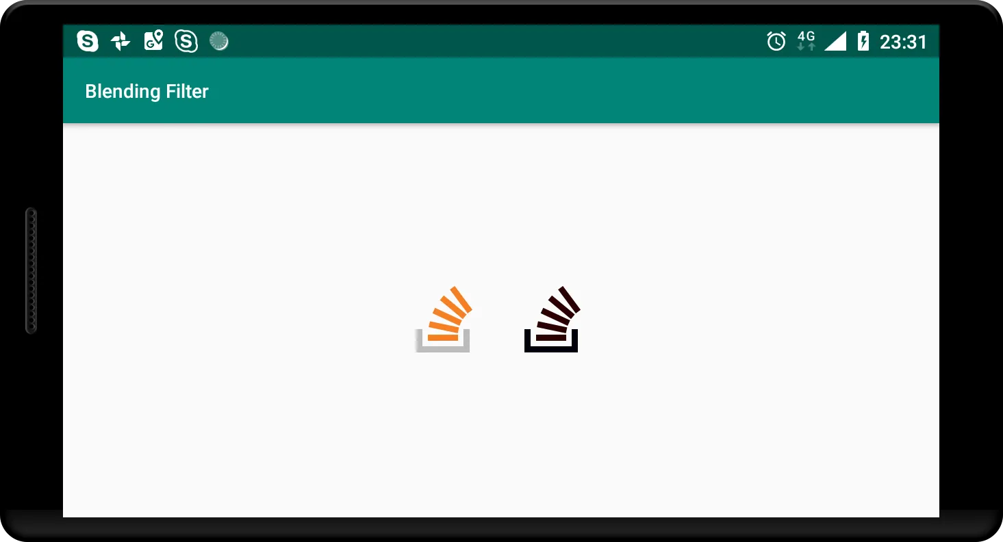
左边是原始图像,右边是混合图像。它们是相同的,正如预期的那样。您还可以使用此方法完全删除特定通道。例如,这里演示了如何删除红色和绿色通道:
代码
BlendingFilterUtil.subtractMatrixColorFilter(bitmap, new float[]{
    1,      0,      0,      0,      0,
    0,      1,      0,      0,      0,
    0,      0,      0,      0,      0,
    0,      0,      0,      1,      0
}, activity, callback);
输出
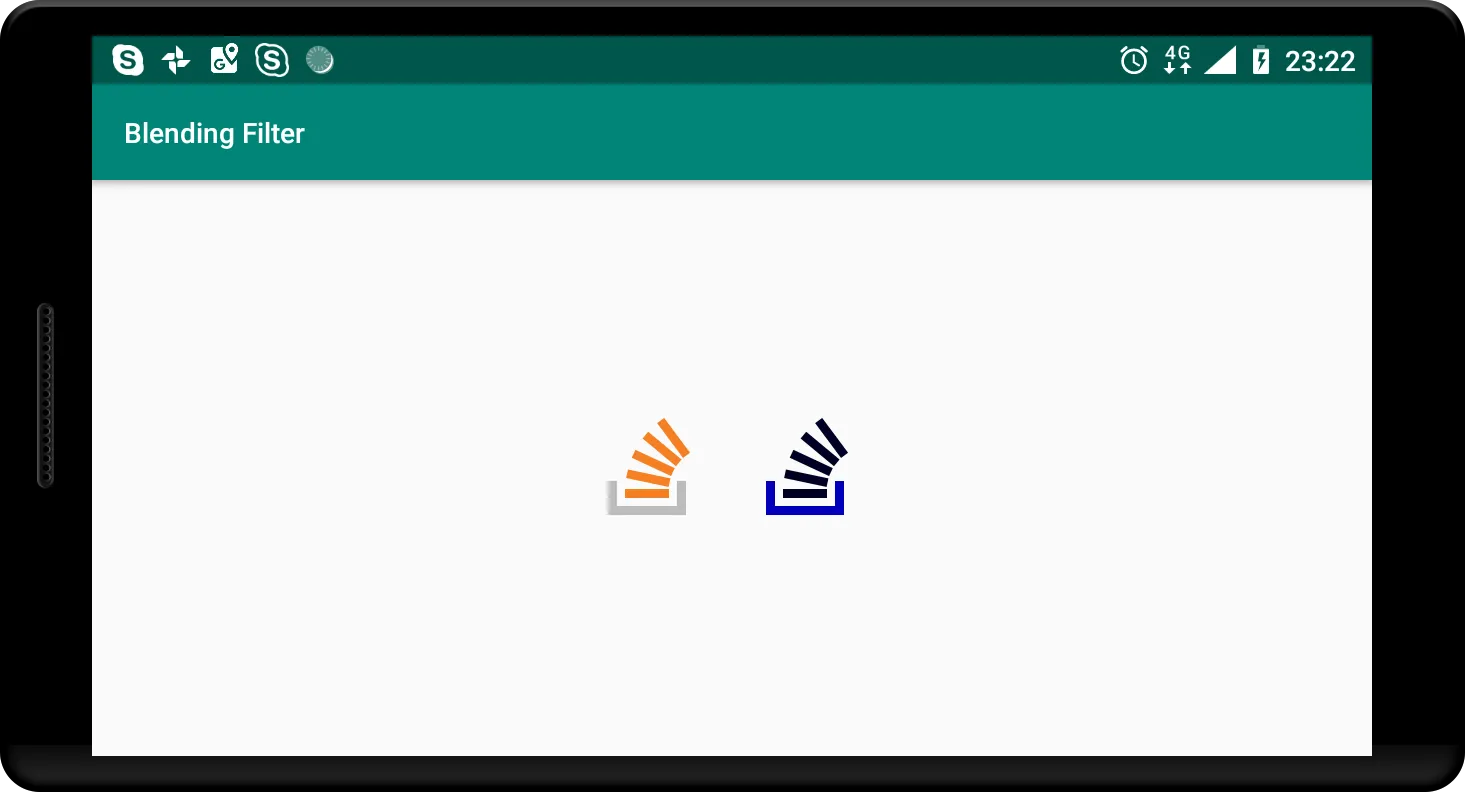
最终,这是问题中给出的过滤器的结果:
代码
BlendingFilterUtil.subtractMatrixColorFilter(bitmap, new float[]{
    0.393f, 0.7689999f, 0.18899999f, 0, 0,
    0.349f, 0.6859999f, 0.16799999f, 0, 0,
    0.272f, 0.5339999f, 0.13099999f, 0, 0,
    0,      0,          0,           1, 0
}, activity, callback);
输出
源代码
如果您在任何步骤上遇到困难,请不要犹豫,参考完整工具的摘要。